Combined detection tool of bearing working condition of box type rotating equipment

A rotating equipment and combined detection technology, which is applied in the direction of mechanical bearing testing, etc., can solve problems such as hidden dangers and malignant equipment accidents, bearings that cannot be visually inspected, and production order impacts, etc., to shorten the time of placement and removal, simple and practical structure, and easy selection of production materials Effect

Active Publication Date: 2017-12-01
HANDAN IRON & STEEL GROUP +1
View PDF8 Cites 0 Cited by
  • Summary
  • Abstract
  • Description
  • Claims
  • Application Information

AI Technical Summary

Problems solved by technology

For example, in the early stage of bearing and gear damage of box-type rotating equipment such as rolling mill reducer and transmission shaft gearbox in hot rolling mills, the online monitoring equipment failed to timely feedback abnormal changes in parameters such as the sound, vibration, and temperature of the bearing due to the interference of on-site working conditions. , but obvious iron filings were found in the oil return filter screen of the concentrated thin oil lubrication used by the bearing; due to the centralized thin oil lubrication, there are many box-type rotating equipment on site. Moreover, some bearings installed in the box-type rotating equipment cannot be visually inspected, which will have a serious impact on the production order. If the equipment damage cannot be detected and eliminated in time, hidden dangers will expand at any time and cause vicious equipment accidents

Method used


Image

  • Combined detection tool of bearing working condition of box type rotating equipment
  • Combined detection tool of bearing working condition of box type rotating equipment
  • Combined detection tool of bearing working condition of box type rotating equipment

Examples


Embodiment Construction

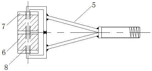
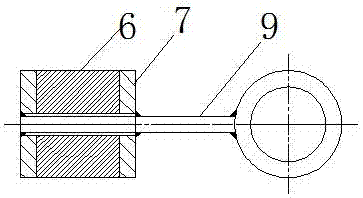
[0021] Figure 1 to Figure 6 It is a schematic diagram of an embodiment of the present invention; as shown in the figure, a box-type rotating equipment bearing working condition combined detection tool of the present invention includes a rolling detection head 1, a fixed detection head 2, a universal adjustment rod 3, and an access hook 4 and a T-shaped hand-held rod 10; the rolling detection head includes a Y-shaped bracket 5, a roller shaft 8, 2 cylindrical hollow magnets 6 and 3 circular metal spacers 7, and the metal spacers 7 are made of stainless steel, and the diameter is the same as that of a cylinder The outer diameter of the hollow magnet 6 is the same; the tail of the Y-shaped support 5 has an external thread, and the ends of the two forks are fixed to a long side of the rectangular frame. The plane where the rectangular frame is located coincides with the plane where the support 5 is located. One long side is the roller shaft 8, and the roller shaft 8 is fixed to t...


PUM


Abstract

The invention relates to a combined detection tool of a bearing working condition of box type rotating equipment. The detection tool comprises a rolling detection head, a fixed detection head, a universal adjusting rod, and an access hook. The rolling detection head consists of a bracket, a roll shaft installed on the bracket, a plurality of cylindrical hollow magnets and a plurality of metal gaskets. The roll shaft is fixed with centers of the plurality of parallel metal gaskets; and after fixation, one cylindrical hollow magnet with the axis overlapped with the roll shaft is clamped between each two adjacent metal gaskets. The fixed detection head includes an annular connecting rod, the cylindrical hollow magnet, and two metal gaskets arranged at the two ends of the cylindrical hollow magnet; the annular connecting rod includes a rod part and an annular tail part; the rod part passes through the axis of the cylindrical hollow magnet is fixed with the centers of the two metal gaskets; and after fixation, the cylindrical hollow magnet is clamped between the two metal gaskets. According to the invention, detection on a bearing working condition can be completed rapidly with high quality in the small internal space of the box type rotating equipment and thus any potential safety hazard of the bearing can be discovered timely, so that the on-line equipment maintenance efficiency is improved.

Description

technical field [0001] The invention relates to a box-type rotating equipment bearing working condition combined detection tool, which belongs to the technical field of mechanical maintenance equipment. Background technique [0002] With the advent of the industry 4.0 era, the structural design and functions of box-type rotating equipment are more diversified. The layout of these box-type rotating equipment is very compact, most of them are closed installation, the internal space is narrow, and various bearings run in the closed box; the good operation of the bearings is a necessary condition to ensure normal production, so it is necessary to frequently check the bearings However, since most of the bearings in the box are equipped with centralized lubricating oil supply devices, and are equipped with oil retaining and dust-proof devices, this affects the online operation detection of the bearings, and many parts cannot be touched by hands. It is invisible to the naked eye. ...

Claims


Application Information

Patent Timeline
Patent Type & Authority Applications(China)
IPC IPC(8): G01M13/04
CPCG01M13/04
Inventor 杨洪牛宇孟令达韩社军孟凡毅耿森谢超
Owner HANDAN IRON & STEEL GROUP
Why Eureka
Try Eureka