
Multi-channel microwave component testing system

A microwave component and test system technology, applied in the direction of measuring electricity, measuring devices, measuring electrical variables, etc., can solve the problems of no control over the structure of the multi-channel microwave component to be tested, no reference, and low test efficiency, so as to improve test efficiency , Reduce production costs, save production and management costs

Inactive Publication Date: 2017-12-01
SOUTHWEST CHINA RES INST OF ELECTRONICS EQUIP
View PDF11 Cites 3 Cited by
  • Summary
  • Abstract
  • Description
  • Claims
  • Application Information

AI Technical Summary

Problems solved by technology

The invention patent "Automatic Test Module and Method for Microwave Components" (CN 105699826 A) proposes a method of connecting the microwave component to the test module through a test fixture to realize automatic testing, but there is no way to control the closure of each channel of the multi-channel microwave component to be tested. Method of constructing and testing a microwave assembly using a channel control module
The invention patent "Automatic Test Method for Multi-channel Microwave Components" (CN104076214A) proposes to use virtual instrument software and virtual instrument hardware to realize functions such as collection, transmission, analysis, processing, display, and storage of test and measurement data, but it does not mention the use of The method of adding a channel control module between the instrument and the software to improve the efficiency is still not high in actual operation.

Method used


Image

  • Multi-channel microwave component testing system
  • Multi-channel microwave component testing system

Examples


Embodiment Construction

[0018] All features disclosed in this specification, or steps in all methods or processes disclosed, may be combined in any manner, except for mutually exclusive features and / or steps.

[0019] Any feature disclosed in this specification, unless specifically stated, can be replaced by other alternative features that are equivalent or have similar purposes. That is, unless expressly stated otherwise, each feature is one example only of a series of equivalent or similar features.

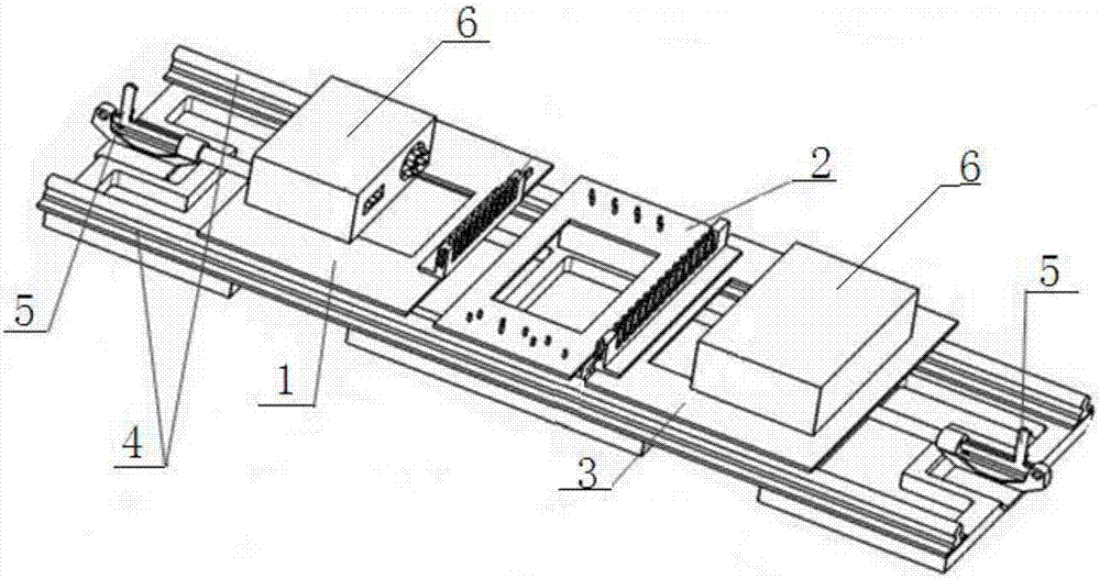
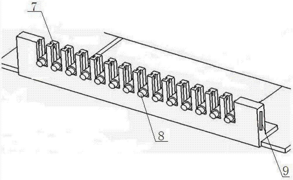
[0020] A multi-channel microwave component testing system, specifically including a channel control module and a test module, the channel control module is used to control the opening and closing of each channel of the multi-channel microwave component to be tested according to test requirements, and the test module is used to test the microwave components to be tested Components; the channel control module includes a control signal sending module, a radio frequency input module, a microwave component...


PUM


Abstract

The present invention discloses a multi-channel microwave component testing system, which comprises a channel control module and a testing module, wherein the channel control module is used for controlling the opening and closing of each channel of the to-be-tested multi-channel microwave component according to the testing requirements and the testing module is used for testing the to-be-tested microwave component. The channel control module comprises a control signal transmitting module, a radio frequency inputting module, a microwave component placing module and a radio frequency outputting module, wherein the radio frequency inputting module and the radio frequency outputting module are detachably and movably connected to the channel control module and the microwave component placing module is detachably fixed and connected with the channel control module. The control signal transmitting module is correspondingly connected with the radio frequency inputting module; and the microwave component placing module is correspondingly connected with the radio frequency inputting module and the radio frequency outputting module; and the radio frequency outputting module is correspondingly connected with the testing module. The testing module is simple in operation, high in testing efficiency and versatile in practice, which is beneficial to the batch testing of multi-channel microwave components.

Description

technical field [0001] The invention relates to the field of microwave component testing, in particular to a multi-channel microwave component testing system. Background technique [0002] Automatic testing of microwave components through test modules is already a highly efficient method at present. The invention patent "Automatic Test Module and Method for Microwave Components" (CN 105699826 A) proposes a method of connecting the microwave component to the test module through a test fixture to realize automatic testing, but there is no way to control the closure of each channel of the multi-channel microwave component to be tested. A method of constructing and testing microwave components using a channel control module. The invention patent "Automatic Test Method for Multi-channel Microwave Components" (CN104076214A) proposes to use virtual instrument software and virtual instrument hardware to realize functions such as collection, transmission, analysis, processing, displ...

Claims


Application Information

Patent Timeline
IPC IPC(8): G01R31/00
CPCG01R31/00
Inventor 邹铁城陈忠睿丁义超马识途肖玉林金涛侯奇峰秦跃利孙毅
Owner SOUTHWEST CHINA RES INST OF ELECTRONICS EQUIP
Learn More