Microwave staring correlated imaging earth observation method

A correlative imaging and microwave staring technology, applied in the field of radar, can solve the problems of long imaging time, large antenna aperture, and high-resolution imaging of geostationary satellite imaging.

Active Publication Date: 2017-12-01
UNIV OF SCI & TECH OF CHINA
View PDF3 Cites 8 Cited by
  • Summary
  • Abstract
  • Description
  • Claims
  • Application Information

AI Technical Summary

Problems solved by technology

However, due to its high orbital altitude, the resolution of the real aperture radar is proportional to the imaging distance. Under such a long imaging distance, a very large antenna aperture is required, and it is difficult for the satellite platform to realize
Moreover, the side length of the imaging area is generally on the order of hundreds of kilometers. If high-resolution imaging is to be performed, the area resolution units are very large, and the number of pulses required for a single imaging is correspondingly large, which will inevitably lead to a longer imaging time. Therefore, geostationary satellites Imaging is difficult to meet the requirements of high-resolution imaging while dynamic monitoring

Method used


Image

  • Microwave staring correlated imaging earth observation method
  • Microwave staring correlated imaging earth observation method
  • Microwave staring correlated imaging earth observation method

Examples


Embodiment Construction

[0015] The technical solutions in the embodiments of the present invention will be clearly and completely described below in conjunction with the accompanying drawings in the embodiments of the present invention. Obviously, the described embodiments are only some of the embodiments of the present invention, not all of them. Based on the embodiments of the present invention, all other embodiments obtained by persons of ordinary skill in the art without making creative efforts belong to the protection scope of the present invention.

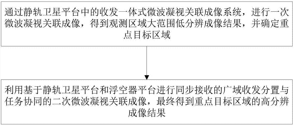
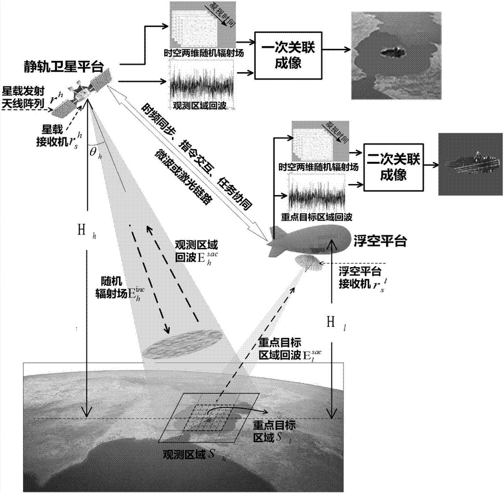
[0016] The embodiment of the present invention provides an earth observation method based on microwave staring associated imaging based on the coordination of geostationary satellites and aerostat platforms, which includes the process of secondary associated imaging; figure 1 As shown, firstly, a microwave staring correlation imaging is performed through the transceiver integrated microwave staring correlation imaging system in the geostationary orb...


PUM


Abstract

The invention discloses a microwave staring correlated imaging earth observation method based on coordination of a geostationary satellite and an aerostat platform. The method comprises steps: through a transmitting and receiving-integrated microwave staring correlated imaging system in a geostationary satellite platform, one-time microwave staring correlated imaging is carried out, a large-range low-resolution imaging result of an observation area is obtained, and a key target area is determined; and wide area bistatic and task coordinated-type secondary microwave staring correlated imaging based on the geostationary satellite platform and the aerostat platform for synchronous receiving is used, and a high-resolution imaging result for the key target area is finally obtained. All-day, all-weather, wide-range and low-resolution observation and investigation and small-range hotspot area key target high-resolution microwave staring imaging can be realized, and the method is applicable to earth remote sensing application scenes such as military battlefield investigation and earthquake relief and disaster relief.

Description

technical field [0001] The invention relates to the field of radar technology, in particular to an earth observation method based on microwave staring correlation imaging based on the cooperation of a geostationary satellite and an aerostat platform. Background technique [0002] Radar Imaging technology is a leap in the history of radar development. It expands the original detection and ranging functions of radar, enabling radar to use the acquired electromagnetic scattering information to obtain a panoramic radar view of the scene. image. [0003] Although Synthetic Aperture Radar (SAR) has high azimuth resolution, its revisit period is long, and it has inevitable inherent disadvantages in scenarios that require long-term continuous staring observation and imaging. The angular resolution of traditional real-aperture radar staring imaging is limited by the aperture of the actual antenna array, which limits its practical application. [0004] Microwave staring correlation ...

Claims


Application Information

Patent Timeline
Patent Type & Authority Applications(China)
IPC IPC(8): G01S13/89G01S7/41
CPCG01S7/411G01S13/89
Inventor 郭圆月王东进陈卫东夏瑞邓杰李泓旻
Owner UNIV OF SCI & TECH OF CHINA
Why Eureka
Try Eureka