Conveying device

A technology for conveying devices and conveyor belts, which is applied in signal transmission systems, instruments, computer control, etc., and can solve problems such as increased equipment and maintenance costs

Inactive Publication Date: 2017-12-01
上海凡宜科技电子有限公司
View PDF5 Cites 2 Cited by
  • Summary
  • Abstract
  • Description
  • Claims
  • Application Information

AI Technical Summary

Problems solved by technology

However, such traditional configurations require separate installation of physical cables to transmit signals and power, resulting in increased equipment and maintenance costs

Method used


Image

  • Conveying device
  • Conveying device
  • Conveying device

Examples


Embodiment Construction

[0056] For the detailed description and technical content of the present invention, please refer to the following detailed description and accompanying drawings as follows, and the accompanying drawings and detailed description are for illustration purposes only, and are not intended to limit the present invention.

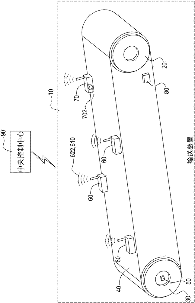
[0057] Please refer to figure 1 , which is a schematic diagram of the delivery device of the present invention. The conveying device 10 of the present invention includes a power main shaft 20, an idler main shaft 30, a conveyor belt 40, a function / energy conversion wireless monitoring device 50, at least one field wireless controller 60, at least one cassette 70 and a stop The conveyor operates the switch 80 .

[0058] The conveyor belt 40 is connected to the power main shaft 20 and the idler main shaft 30, so that when the power main shaft 20 rotates, the power main shaft 20 can drive the idler main shaft 30 through the conveyor belt 40; the function / function co...


PUM


Abstract

The invention provides a conveying device comprising a power spindle, an idle wheel spindle, a conveyer belt, a work/energy conversion wireless monitoring device and at least one field wireless controller. The field wireless controller is used for sensing the operation condition of the conveying device to generate sensing data and wirelessly transmit the sensing data to the work/energy conversion wireless monitoring device. The work/energy conversion wireless monitoring device comprises a power generator, a battery, a rotating speed measurement sensor, a microprocessor and a transmission antenna. The power generator is coupled with the idle wheel spindle. The power generator generates power by the rotating motion of the idle wheel spindle. The battery is electrically connected with the power generator. The battery receives and stores the power generated by the power generator. The rotating speed measurement sensor is used for measuring the rotating speed of the idle wheel spindle.

Description

technical field [0001] The invention relates to a conveying device, in particular to a conveying device with a wireless communication function. Background technique [0002] The industry often uses tension belts as conveying equipment. The belt will naturally become longer after being used for a long time. When the length of the belt exceeds a certain limit, the driving wheel of the conveying equipment will rotate, and the passive idler wheel supported by the other end will not rotate synchronously. If the user If the position of the idler is not found and adjusted in real time, the belt is tightened so that the rotation speed of the idler is synchronized with that of the driving wheel, and the belt conveyor will only rotate independently of the driving wheel, and the belt will be rubbed at a fixed point. After a period of time, the belt will become warm. The liter burns at the end and breaks, and production will be interrupted. If the combustion environment is in a high du...

Claims


Application Information

Patent Timeline
Patent Type & Authority Applications(China)
IPC IPC(8): G05B19/042G08C17/02
CPCG05B19/0428G05B2219/24215G08C17/02
Inventor 王仁舜陈俊宏王志文侯宜良郑兆凱
Owner 上海凡宜科技电子有限公司
Why Eureka
Try Eureka