
Intelligent firefighting control system based on Internet technology

A technology of control system and Internet, applied in general control system, control/regulation system, service based on location information, etc., can solve the problem of indetermination of the location and number of trapped persons, complex design of fire alarm system, unstable alarm system, etc. problems, to achieve the effect of solving the aging of lines, reducing casualties and property losses, and improving transmission speed and efficiency

Inactive Publication Date: 2017-12-01
JILIN JIANZHU UNIVERSITY
View PDF5 Cites 2 Cited by
  • Summary
  • Abstract
  • Description
  • Claims
  • Application Information

AI Technical Summary

Problems solved by technology

[0004] The technical problem to be solved by the present invention is: in order to overcome the complex design of the fire alarm system in the prior art, poor anti-interference ability, harsh construction requirements, slow response, possible burnout of the line after a fire occurs, and the inability to determine the position and number of trapped persons Shortcomings and deficiencies, etc., provide a new type of intelligent fire control system based on Internet technology, through the use of ZigBee wireless positioning network, alarm and linkage control, and communication system design, the fire information, fault information, and normal information in the monitoring area are sent to The upper manager can grasp the situation of the room in real time. The present invention overcomes the instability of the alarm system in the prior art, the difficulty of maintenance, and the inability to realize the positioning of the trapped personnel to generate the best escape route, and significantly reduces the installation cost. It has a strong market Competitiveness

Method used


Image

  • Intelligent firefighting control system based on Internet technology

Examples


Embodiment Construction

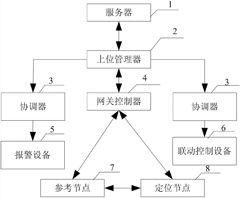
[0018] Such as figure 1 As shown, the intelligent fire control system based on Internet technology includes a server 1, an upper manager 2, a coordinator 3, a gateway controller 4, an alarm device 5, a linkage control device 6, a reference node 7 and a positioning node 8, wherein the reference node 7 Arranged on the ceiling of the room in the building, the reference node 7 includes a smoke sensor, a temperature sensor and a CC2530 chip, the smoke sensor and the temperature sensor are connected to the CC2530 chip in communication, and the reference node 7 carries a smoke sensor and a temperature sensor to monitor the installation environment For the smoke and temperature parameters in the reference node 7, the information can be sent to the gateway controller 4, and personnel can be located. Specifically, the information packet of the reference node 7 position coordinates and RSSI value is transmitted to the positioning node 8, and the RSSI value is the signal strength of the CC...


PUM


Abstract

The invention discloses an intelligent firefighting control system based on Internet technology, and belongs to the intelligent building field. The intelligent firefighting control system comprises a server, an upper manager, a coordinator, gateway controllers, alarming equipment, linkage control equipment, reference nodes, and positioning nodes. The upper manager is connected with the server, the coordinator, and the gateway controllers by CAN buses. The coordinator is connected with the alarming equipment and the linkage control equipment by a ZigBee wireless sensing network. The gateway controller is disposed on ever floor, and the gateway controllers are connected together by the CAN buses, and are connected with the ZigBee wireless sensing network by the reference nodes and the positioning nodes, and the reference nodes and the positioning nodes are connected together by the ZigBee wireless sensing network. A positioning system is combined with alarming and firefighting linkage control, and after the alarming, the linkage control equipment is started, and then by using the wireless positioning system, a fire hazard area is determined accurately, and therefore after firefighters receive alarming information, the firefighters can search and rescue trapped people timely and accurately.

Description

technical field [0001] The invention belongs to the field of intelligent buildings, in particular to an intelligent fire protection system. Background technique [0002] In intelligent buildings, the intelligence of the fire protection system is very important and plays an important role in reducing losses after a fire occurs. Due to the development of economy and the advancement of science and technology, there are more and more types of electrical equipment, and there are more and more reasons for fires. Not only is the use of fire and electricity in the kitchen easy to cause fires, but the misuse of electrical equipment also increases the risk of fires. incidence rate. At present, the nationally recognized fire protection system must use wired communication. After a fire occurs, the detector detects a fire signal, which is transmitted to the fire control center through the line, and the alarm equipment and linkage control equipment are activated to perform alarm and fire...

Claims


Application Information

Patent Timeline
Patent Type & Authority Applications(China)
IPC IPC(8): G05B19/048H04W4/00H04W4/02H04W4/04H04L29/08G08B17/06G08B17/10
CPCH04L67/125H04W4/023G05B19/048G08B17/06G08B17/10H04L67/52
Inventor 韩成浩王蕊田鹏王龙旭张伟利孙晓罡杨成佳满宴辰李闯胡成海马刚高磊吕贵明
Owner JILIN JIANZHU UNIVERSITY
Learn More