
Dynamic texture recognition method based on two bipartite graph

A technology of dynamic texture and recognition method, applied in image data processing, character and pattern recognition, image analysis and other directions, can solve problems affecting optical flow calculation, loss of sports field, etc., and achieve the effect of simple segmentation algorithm and good effect.

Inactive Publication Date: 2017-12-01
苏州珂锐铁电气科技有限公司
View PDF11 Cites 1 Cited by
  • Summary
  • Abstract
  • Description
  • Claims
  • Application Information

AI Technical Summary

Problems solved by technology

However, it is subject to local motion constraints, so for the motion of low-texture and texture-free objects, the motion field inside the object will be lost, that is, the background that was originally covered in the two frames before and after appears due to foreground motion, which affects the optical flow calculation.

Method used


Image

  • Dynamic texture recognition method based on two bipartite graph
  • Dynamic texture recognition method based on two bipartite graph
  • Dynamic texture recognition method based on two bipartite graph

Examples


Embodiment 1

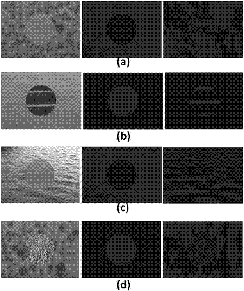
[0074] In this embodiment, the dynamic texture segmentation database is 100 dynamic texture videos obtained through artificial synthesis, in which only two kinds of dynamic textures appear. image 3 The middle left column gives examples of texture images in the database. The results obtained by segmentation with chaotic eigenvectors are shown in image 3 middle column. The results obtained by segmenting the pixel time series are shown in image 3 Center right column. It can be seen from the experimental results that the results obtained by using chaotic eigenvector segmentation are better than those obtained by using pixel time series. Shown in the figure is the preliminary result of segmentation, and the noise in some places can be improved by the morphology in image processing.

Embodiment 2

[0076] This embodiment is synthesized by adding flames on the water surface. The dynamic flame constantly changes position. Figure 4 The segmentation results are given in . On the left is the picture in the original video, in the middle is the segmentation result obtained by using the chaotic feature vector as the feature, and on the right is the segmentation result obtained by using the pixel time series as the feature.

Embodiment 3

[0078] In this implementation, it is dense scene data. Intensive scenes exist widely in real life, especially large gatherings. It is quite difficult to track, recognize and understand dense scenes, but it has important practical application value. We do a preliminary study of this problem by segmenting dense scenes. Figure 5 The middle left column gives examples of texture images in the database. The results obtained by segmentation with chaotic eigenvectors are shown in Figure 5 middle column. The results obtained by segmenting the pixel time series are shown in Figure 5 Center right column. Figure 5 (a) shows the crowd moving in a circle in Mecca. The crowd in the video has two movement directions, some moving clockwise and some moving counterclockwise. The motion of the two parts is obtained by a segmentation algorithm. Figure 5 (b) shows dense traffic flow. Figure 5 Shown in (c) is the flow of traffic traveling on the highway. Figure 5A video of dense crow...


PUM


Abstract

The invention specifically relates to a dynamic texture recognition method based on a bipartite graph and is designed for improving the accuracy of dynamic texture recognition. According to the dynamic texture recognition method based on a bipartite graph, firstly a chaotic feature vector is extracted from each pixel time sequence in a dynamic texture video, and thus the video becomes a chaotic feature vector matrix. Then, the hybrid Gauss method is used to segment the chaotic feature matrix, a similarity degree between two dynamic textures is compared with a metric, then a graph model is established through the similarity comparison. Finally, the Hungarian algorithm is used to achieve the purpose of dynamic texture recognition. The method can be applied to various civil and military systems such as face recognition and military target tracking and recognition systems, and the method has a broad market prospect and application value.

Description

technical field [0001] The invention relates to the technical field of computer pattern recognition, in particular to a dynamic texture recognition method based on a bipartite graph. Background technique [0002] The traditional bag-of-words model will affect the clustering result due to the size of the codebook, and then affect the feature histogram, thereby affecting the recognition rate. To solve this problem, a lot of research has been done in the field of pattern recognition. A matching method based on image content can solve this problem. Content-based image and video retrieval, recognition is an important part of computer vision research. [0003] Video segmentation is a research hotspot in the field of computer vision and pattern recognition. Accurately classifying different motion patterns in videos has broad application prospects in both civilian and military applications. Such as the segmentation of dense crowds, different motion patterns can be obtained, whic...

Claims


Application Information

Patent Timeline
IPC IPC(8): G06K9/00G06T7/246G06T7/40
CPCG06T7/246G06T7/40G06V20/48G06V20/41G06V20/46
Inventor 洪金剑王勇
Owner 苏州珂锐铁电气科技有限公司
Learn More