
Method for participating in automatic generation control by controllable loads

An automatic power generation control and load technology, which is applied in the direction of instruments, data processing applications, information technology support systems, etc., can solve the problems of small controllable load reserve capacity, long control cycle, and reduced efficiency, so as to improve comprehensive regulation performance and improve Utilization rate and the effect of reducing peak-to-valley difference

Active Publication Date: 2017-12-01
STATE GRID LIAONING ELECTRIC POWER RES INST +2
View PDF17 Cites 27 Cited by
  • Summary
  • Abstract
  • Description
  • Claims
  • Application Information

AI Technical Summary

Problems solved by technology

[0010] The above invention provides the feasibility of controllable loads to participate in grid regulation, which can improve the grid regulation performance to a certain extent, but because the adjustment reserve capacity of controllable loads is relatively small, the adjustment ability for large power grids is limited. It is difficult for the load regulation scheme to have a huge impact on the high-voltage and high-power transmission network, and it must be adjusted in conjunction with the power supply side to achieve the best benefits
In addition, under the existing technical conditions, the adjustment of the controllable load by the dispatcher master station can be implemented by dispatchers manually ordering or issuing dispatching plans, but the manual ordering method cannot adapt to the continuous growth of the number of controllable loads. A large number of controllable loads will inevitably lead to a decrease in efficiency through manual regulation; the controllable loads are controlled by issuing a dispatch plan. This method has a long control period and poor flexibility, and cannot meet the needs of real-time regulation of the power grid.

Method used


Image

  • Method for participating in automatic generation control by controllable loads
  • Method for participating in automatic generation control by controllable loads

Examples


Embodiment Construction

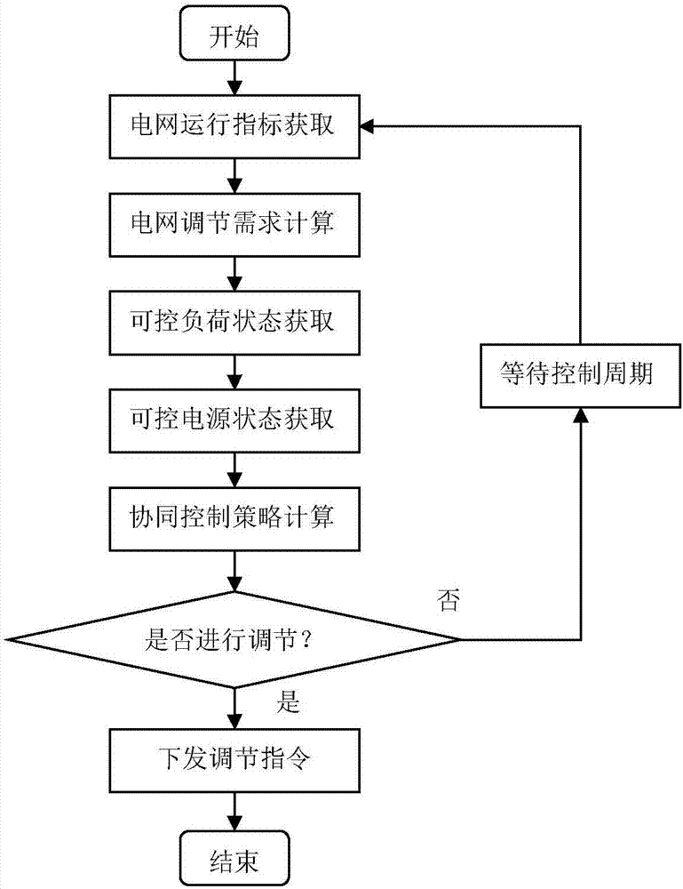
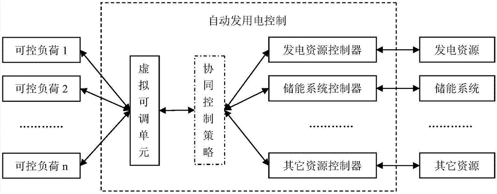
[0031] According to the above content, the realization method of controllable load participating in automatic power generation control is given. The details are as follows.

[0032] 1. Hardware configuration

[0033] On the basis of the existing power grid dispatching automation system equipment, the hardware facilities are transformed, including the following:

[0034](1) Load information collection facilities are added to the dispatching master station on the grid side to obtain the operating status parameters of each controllable load in real time;

[0035] (2) Add a controllable load response terminal on the distribution network side, receive the control commands issued by the dispatching master station in real time, submit them to the load power adjustment equipment for execution, and send the real-time load information to the master station.

[0036] (3) The communication channel adopts the existing power dispatching data network.

[0037] 2. Software Configuration

...


PUM


Abstract

The invention discloses a method for participating in automatic generation control by controllable loads. Aiming at the conditions of increased adjustment complexity of a power grid and more diversified regulation and control means caused by the novel controllable loads in the power grid, the scattered controllable loads are aggregated and are enabled to be equivalent to virtual adjustable units whose outputs are negative values, parameters including an adjusting threshold and an adjusting range thereof are automatically calculated, the controllable loads are brought into a conventional automatic generation control system and participate in the adjustment of the power grid with other energies together, the automatic generation control is developed towards automatic power generation and consumption combined control, centralized cooperative control of the adjustable units of the whole grid is realized, the comprehensive regulation and control effect of the power grid is achieved to the maximum, and technical means is provided for interaction of the energies, the grid, and the loads.

Description

technical field [0001] The invention relates to the field of power grid dispatching control, in particular to a method for controllable loads to participate in the automatic power generation control of the power grid. Background technique [0002] With the development of power grid construction and the emergence of various new controllable loads (such as centralized electric boiler heating, electric vehicle charging stations, large-scale cold storage, etc.), the complexity of power grid regulation has increased, and the regulation methods have become more diverse. Power sources and controllable loads are distributed in different locations in the power grid, and centralized control of these distributed adjustable units can help maximize the role of power grid comprehensive regulation. [0003] Automatic power generation control is an important and basic function of the power grid dispatching automation system. It is responsible for the regulation of important indicators such ...

Claims


Application Information

Patent Timeline
Patent Type & Authority Applications(China)
IPC IPC(8): G06Q10/06G06Q50/06
CPCG06Q10/0631G06Q50/06Y04S50/16
Inventor 葛维春卓峻峰谭洪恩张宏宇李家珏
Owner STATE GRID LIAONING ELECTRIC POWER RES INST
Learn More