Fire field monitoring and detection system and fire field monitoring and detection method
A detection system and on-site monitoring technology, applied in fire alarms that rely on smoke/gas effects, advanced technology, nan, etc., can solve the problems of insufficient scalability, lack of flexibility and dependence on the monitoring system, and reduce the sensor The effect of network congestion
Inactive Publication Date: 2017-12-01
SICHUAN REX SMART TECH CORP LTD
8 Cites 1 Cited by
AI-Extracted Technical Summary
Problems solved by technology
Traditional monitoring systems lack flexibility, rely too much on wire and cable-based communication facilities, and lack scalability
Even the latest wireless fire monitoring system has defects such as high cost and single node type
For example, the single use of smoke sensors is susce...
Method used
[0036] The wireless sensor network is a resource-constrained network, and the present invention reduces the transmission of redundant data in the network based on the fire transmission probability threshold algorithm. First calculate the weighted value coefficient of each sensor measurement value corresponding to each sensor node at the bottom layer, then substitute the weighted value coefficient into...
Abstract
The invention provides a fire field monitoring and detection system and a fire field monitoring and detection method. The system comprises a WSN communication network and a fire alarm monitoring platform, wherein the WSN network comprises an aggregator, a terminal, and a router; the terminal comprises a field monitoring node and a mobile terminal node; the router comprises a routing node for routing information, region positioning nodes are customized, and each region positioning node has a unique routing ID for realizing a region positioning function; the aggregator is used for information aggregation and format conversion; and the fire alarm monitoring platform is used for displaying data in real time. According to the fire field monitoring and detection system and the fire field monitoring and detection method provided by the invention, multiple monitoring means are adopted to comprehensively realize accurate detection on smoke and dust in the fire field, the number of needed sensor is fewer, and the sensor network congestion is reduced.
Application Domain
Power managementNetwork topologies +3
Technology Topic
Network congestionReal-time computing +5
Image
Examples
- Experimental program(1)
Example Embodiment
[0010] The following is attached to illustrate the principle of the present invention Figure one A detailed description of one or more embodiments of the present invention is provided together. The present invention is described in conjunction with such an embodiment, but the present invention is not limited to any embodiment. The scope of the present invention is limited only by the claims, and the present invention covers many alternatives, modifications and equivalents. In the following description, many specific details are set forth in order to provide a thorough understanding of the present invention. These details are provided for the purpose of example, and the present invention can be implemented according to the claims without some or all of these specific details.
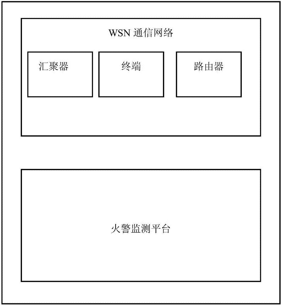
[0011] One aspect of the present invention provides a fire field monitoring and detection system and method. figure 1 It is a flowchart of a fire field monitoring and detection system and method according to an embodiment of the present invention.
[0012] The system of the present invention includes the underlying WSN communication network and the fire alarm monitoring platform. The WSN network includes aggregators, terminals and routers. The terminals include on-site monitoring nodes and mobile terminal nodes. The router includes routing nodes for routing information, and customized regional positioning nodes. Each regional positioning node has a unique routing ID to implement the regional positioning function. The aggregator implements information aggregation and format conversion. The fire alarm monitoring platform displays the data in real time. The administrator can open and close all on-site monitoring nodes through the aggregator. The opening and closing are operations on the monitoring status flag bit in the node. When the node is shut down and enters the sleep state, only the system start command can wake up the node. After receiving the turn-on command from the converger, the field monitoring node immediately applies for the regional positioning node ID from the regional positioning node closest to the node. After successfully receiving the regional positioning node ID, the self-monitoring status is set to open, and the open success command is returned to the aggregator at the same time. When the field monitoring node receives the shutdown system command, it marks the fire alarm monitoring status as shutdown, and then returns the shutdown success command to the aggregator. If the distance between the aggregator and the field monitoring node is too long, the information will be transferred through the regional positioning node and the router.
[0013] In the on state, when the smoke and dust concentration exceeds the standard, the sensor module will output a low level. The on-site monitoring node detects the smoke and dust, and at the same time sends alarm information to the aggregator and mobile terminal node. The information includes the alarm level and the alarm location. The aggregator parses and converts WSN data frames into serial frames, and obtains the situation of the entire monitoring area in real time through the upper computer client. After receiving the information, the mobile terminal node will send out an audible and visual alarm and display on the screen. When the alarm is eliminated, the alarm can be cleared through the on-site monitoring node, and the on-site monitoring node can be reset to the monitoring state.
[0014] When a person is traveling and the mobile terminal node equipped with it detects a gas leak, the mobile terminal node will issue an audible and visual alarm and at the same time send an alarm command to the concentrator. If the person holding the device cannot resolve the alarm, the node can send a support request containing the location information of the area where the node is located to other personnel through the node. After receiving the information, other traveling mobile terminal nodes can quickly rush to support.
[0015] The field monitoring node includes DSP module, power management module, antenna, crystal oscillator, buzzer, image acquisition module and sensor module. The image acquisition module realizes fire alarm monitoring and early warning based on smoke and dust images. Two sensor modules 1 and 2 are used in the field monitoring node, and one sensor 1 has an independent power management module. When both sensors 1 and 2 are at low level, that is, it is set to high-risk state; when sensor 1 is alarming and sensor 2 is high, it is set to medium-risk state; when sensor 1 is high and sensor 2 is When the low level is alarming, it is set to the suspected risk state. The mobile terminal nodes are staffed and can move freely within the target area, including DSP modules, power management modules, antennas, crystal oscillators, buzzers, buttons, LCD modules, and sensor modules. The aggregator is responsible for establishing the network, and at the same time gathering and processing the monitoring information from the underlying network. The regional positioning node adds a positioning function to the routing node.
[0016] The WSN-based protocol stack initializes and starts the polling operating system in the system. The operating system is responsible for the operation of the entire system and implements the scheduling and management of tasks. According to the task priority from high to low, it is detected whether there is a fire event in the task. If a fire event occurs, the corresponding processing function is called, and the detection is continued after the processing is completed.
[0017] The field monitoring node part receives the regional positioning node ID application request after the aggregator opening command, and after successfully opening or closing, the feedback to the aggregator and the alarm information transmission to the mobile terminal node and the aggregator after an alarm occurs. The operating system polls and checks the task event flag bit array. When the application layer event is set, if it receives an open command, it will apply for the node ID from the nearest positioning node in the form of unicast. At the same time, it feeds back a successful start command to the aggregator in unicast transmission mode. When the operating system enters the next round of polling, if the analysis finds that it receives the return route ID command, it will indicate the node's own monitoring status as on, and display it to the display screen, and then feedback the successful opening to the coordinator in the form of unicast.
[0018] In the state of system start-up monitoring, when the operating system detects that the hardware layer event flag is set, it will determine which event has occurred. If an alarm event occurs, analyze the hardware-level event, and after determining the risk level, send various levels of alarm commands to the aggregator, and send various levels of regional positioning node IDs to all mobile terminal nodes in group addressing transmission mode. Alarm command.
[0019] The mobile terminal node realizes its own monitoring of fire hazards and sends out information for help, and secondly processes the received alarm information of the on-site monitoring node or information for help from other personnel. If the operating system finds that the hardware layer event is set when polling the event flag bit array, it will analyze the event that occurred. If the sensor acquisition module outputs a low-level alarm event, it will send out an audible and visual alarm and display the risk information and area location to the display screen. In addition, after applying for the area positioning node ID, it will send the personnel node alarm command to the converger in unicast form. . The effective commands received by the mobile terminal node include the on-site monitoring node alarm command and the request support command.
[0020] The image acquisition module of the site monitoring node performs smoke and dust monitoring based on the captured video images. In the video image, smoke and dust are characterized by the increase in the number of video frames and the area increases until the smoke and dust concentration is low enough to be unable to capture. The geometric feature extracted by the present invention divides the target area into three parts longitudinally, and counts the number of bright spots in the three parts: bottom Mb, middle Mm, and top Mt.
[0021] Then the present invention extracts the directional characteristics of the target area, and first performs the color space pre-processing on the target image, that is, converts the image to be processed into a gray image:
[0022] Gray=0.3R+0.59G+0.11B
[0023] For the image after color space processing, obtain the gradient amplitude and the angle value of the gradient direction of each pixel in the image to be processed, and calculate the upper, lower, left and right pixels of the pixel I(x, y) respectively , The gradient formula is:
[0024] G x (x,y)=I(x+1,y)-I(x-1,y)
[0025] G y (x,y)=I(x,y+1)-I(x,y-1)
[0026] G(x,y)=(G x (x, y) 2 +G y (x, y) 2 ) 1/2
[0027] θ(x,y)=arctan(G x (x,y)/G y (x,y))
[0028] The classification module generated by SVM is used for image recognition of smoke and dust. First, a large number of positive samples, namely, smoke and dust samples, and negative samples, that are samples without smoke and dust, are selected. Through the image acquisition of the video stream, the obtained continuous video frames are intercepted to take out positive and negative samples, the directional features of the positive and negative sample sets are extracted respectively and combined into a multi-dimensional feature vector, which is input into the SVM to learn, and a classification module is generated . Identify the target area extracted above, and convert the coordinates of the identified smoke area to the original video frame, and then mark the location of the smoke, so that the area where the smoke is located can be identified.
[0029] If the area growth rate of the suspected smoke area detected between consecutive frames or within a period of time is used to measure the spread of the smoke area. It can also eliminate false alarms caused by stationary objects, effectively improving the recognition rate of smoke and dust. T i The area of the suspected smoke and dust area at the moment is recorded as A i , T i+1 The area of the suspected smoke and dust area at the moment is recorded as A i+k , Then A i+k -A i Means t i+1 Time relative to t i Changes in the area of suspected smoke and dust at all times:
[0030] ΔA=(P i+k -P i )/k
[0031] Where P i Represents the t i The total number of pixels in the suspected smoke area of the image at the moment, P i+k T i+k The number of pixels in the suspected area of smoke at a time, then k represents the number of frames between the two images.
[0032] In order to further normalize the value of the area growth rate, the present invention calculates its relative difference, that is, calculates the absolute area growth rate of smoke and dust:
[0033] m i =(P i+k -P i )/k P i
[0034] For the possible absolute area growth rate that is negative, the average value method is further applied to weaken the influence of air flow. That is to find the nearest n area growth rate m from the current moment 1 , M 2 ,...,m n , Use its average value to express the absolute area growth rate at the current moment, as a criterion for distinguishing smoke and dust from other moving objects:
[0035]
[0036] The wireless sensor network is a resource-constrained network. The present invention is based on the algorithm of fire transmission probability threshold to reduce the transmission of redundant data in the network. First calculate the weighted value coefficient of each sensor measurement value corresponding to each sensor node at the bottom layer, then substitute the weighted value coefficient into the regression algorithm to calculate the fire occurrence rate of each sensor node, and finally obtain the network transmission according to the fire occurrence rate threshold Probability. That is, the data of sensor nodes whose fire rate is less than the threshold is not transmitted to the transmission node, thereby reducing the number of communications between nodes in the entire network.
[0037] The first step of the algorithm is to integrate the raw data of sensor nodes to obtain the weighted coefficient of each scalar sensor value. The second step is to obtain the fire occurrence rate value of each sensor node, and then determine the threshold range according to the characteristics of the regression model. The third step is to calculate the transmission probability in the corresponding cluster based on the threshold of the fire occurrence rate.
[0038] In the first step, the formula for integrating the weighted coefficients of all sensor measurement values of a certain sensor node at time t is:
[0039]
[0040] Among them, X*(t) is the weighted average integration result of the weighted average value of each sensor measurement value of the sensor node at time t, X(t)=((x 1 (t))),(x 2 (t)),...(x N (t))) is the measured value obtained by N sensors collecting data on the surrounding environment at time t, that is, the input data vector of the weighted average; W(t)=((w 1 (t))),(w 2 (t)),...(w N (t))) is a vector composed of the weight coefficients of each sensor measurement value of the weighted mean value at time t, which represents the relative importance of each sensor measurement value to the global estimate of the fire occurrence rate around the node.
[0041] The steps of data integration include: First, regularize the raw data from the sensor:
[0042]
[0043] The sensor measurement value x i (t) as a normally distributed random variable, denoted as x i (t)~N(μ,σ 2 ). The normal distribution function is:
[0044]
[0045] among them K is the number of measurements.
[0046] Step 3: When a fire occurs, the sensor measurement value changes suddenly, x i (t) will deviate from μ, use f(x i (t)) and f(μ i The Euclidean distance between) represents the weight coefficient of the weighted average of the sensor measurement values of the sensor node at time t, and the Euclidean distance between them is:
[0047]
[0048] Get the weight coefficient of the sensor measurement value:
[0049]
[0050] Where w i (t) satisfy:
[0051] Sensor measured value x i (t) weight coefficient w i (t) is proportional to the probability of fire occurring around the sensor node.
[0052] Define the probability value of the binary outcome f(Z i ):
[0053]
[0054] Where Z i Is a linear function of independent variables:
[0055] Z i =B 0 +B 1 x 1 +B 2 x 2 +...+B i x i , Where B i Is the sensor measured value x i the weight of.
[0056] Therefore, the fire occurrence rate of sensor nodes is predicted as follows:
[0057]
[0058] Where w T , W H Is the weight of temperature and humidity on fire rate; T 0 , H 0 Is the maximum value of temperature and humidity collected by the sensor in a safe state; b is the regression constant; a is the coefficient of change.
[0059] Further, the transmission probability is the number of data packets sent to the cluster head node by the sensor node in the wireless sensor network within a fixed time. If there are M sensor nodes in a cluster, within a fixed time T, each sensor node collects group C data and sends m i (t) data packets, calculate the transmission probability PT in a cluster network within time T:
[0060]
[0061] In summary, the present invention provides a fire field monitoring detection system and method, which adopts multiple monitoring methods to comprehensively realize accurate detection of fire field smoke and dust, requires fewer sensors, and reduces sensor network congestion.
[0062] Obviously, those skilled in the art should understand that the above-mentioned modules or steps of the present invention can be implemented by a general computing system, and they can be concentrated on a single computing system or distributed on a network composed of multiple computing systems. Above, optionally, they can be implemented with program codes executable by the computing system, so that they can be stored in the storage system and executed by the computing system. In this way, the present invention is not limited to any specific combination of hardware and software.
[0063] It should be understood that the foregoing specific embodiments of the present invention are only used to exemplarily illustrate or explain the principle of the present invention, and do not constitute a limitation to the present invention. Therefore, any modifications, equivalent substitutions, improvements, etc. made without departing from the spirit and scope of the present invention should be included in the protection scope of the present invention. In addition, the appended claims of the present invention are intended to cover all changes and modifications that fall within the scope and boundary of the appended claims, or equivalent forms of such scope and boundary.
PUM


Description & Claims & Application Information
We can also present the details of the Description, Claims and Application information to help users get a comprehensive understanding of the technical details of the patent, such as background art, summary of invention, brief description of drawings, description of embodiments, and other original content. On the other hand, users can also determine the specific scope of protection of the technology through the list of claims; as well as understand the changes in the life cycle of the technology with the presentation of the patent timeline. Login to view more.