
System for flushing pipe plumbing using microbubbles, method therefor, and ship or maritime plant having same

A flushing system and pipe system technology, which is applied in the field of pipe flushing systems using ultra-fine foam, can solve problems such as incomplete removal of scale in pipe sections, damage to filters or water filters, inability to completely remove scale, etc., to achieve extended Effects of life and efficiency, increase of Reynolds number, and maximization of process efficiency

Inactive Publication Date: 2017-12-01
(株)三英菲尔-科技 +1
View PDF8 Cites 0 Cited by
  • Summary
  • Abstract
  • Description
  • Claims
  • Application Information

AI Technical Summary

Problems solved by technology

[0009] The scale (rust, blasting ball, etc.) inside the exhaust pipe is firmly adhered to the inside of the exhaust pipe by the moisture inside the exhaust pipe. Therefore, it cannot be completely cleaned by only supplying compressed air to the inside of the exhaust pipe. descaling
[0010] In addition, the scale inside the pipe section was not completely removed, and when it was delivered to the construction site for trial operation, the filter or strainer connected to the pipe was damaged. In particular, steam blowing (Steam Blowing) or The problem that important processes such as oil flushing (Oil Flushing) are delayed

Method used


Image

  • System for flushing pipe plumbing using microbubbles, method therefor, and ship or maritime plant having same
  • System for flushing pipe plumbing using microbubbles, method therefor, and ship or maritime plant having same
  • System for flushing pipe plumbing using microbubbles, method therefor, and ship or maritime plant having same

Examples


Embodiment Construction

[0069] Hereinafter, an embodiment of the present invention will be described in detail with reference to the drawings.

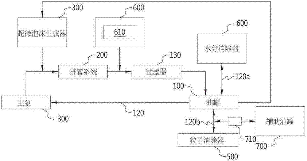
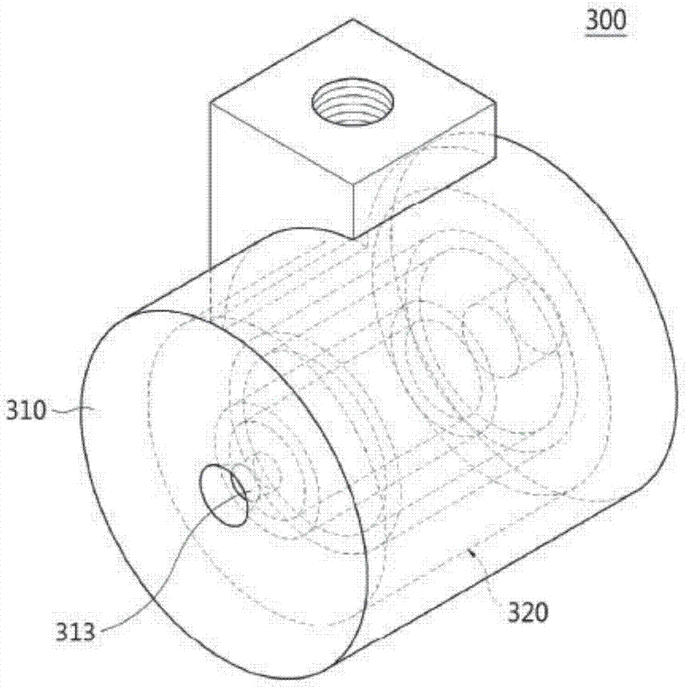
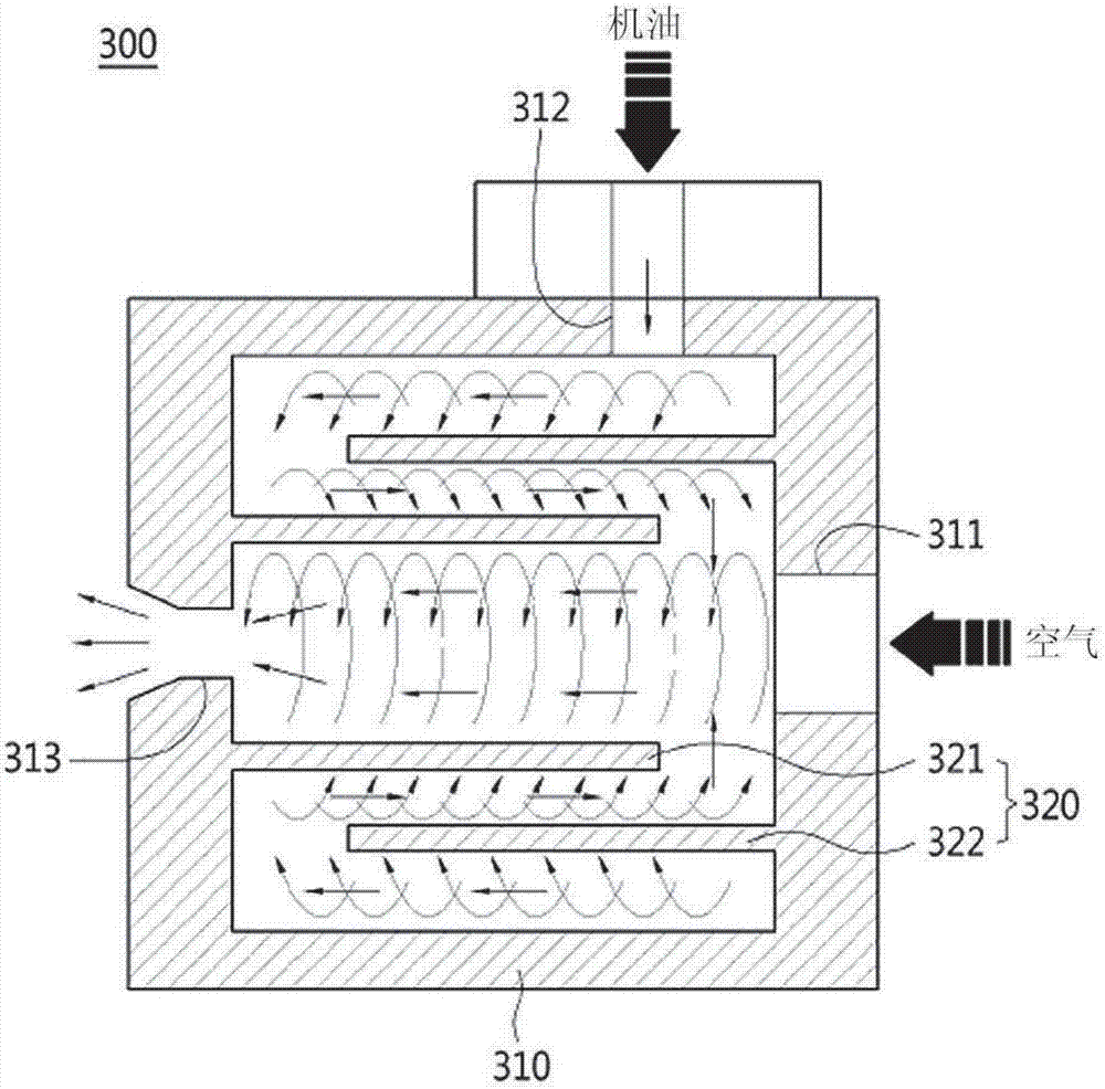
[0070] figure 1 It is a flow chart representing the pipe flushing system according to the present invention; figure 2 It is an internal projection perspective view of the ultra-fine bubble soo generator of the pipe flushing system according to the present invention; image 3 for figure 2 sectional view of Figure 4 It is a structural diagram showing the moisture eliminator of the drainage pipe flushing system according to the present invention; Figure 5 It is a diagram showing the internal structure of the particle eliminator of the pipe flushing system according to the present invention; Image 6 to express the basis Figure 5 Cross-sectional view of the electrode of the particle eliminator.

[0071] Figure 7 It is a block diagram representing a pipe flushing method according to the present invention; Figure 8 It is a block diagram representing...


PUM


Abstract

The present invention relates to a system for flushing pipe plumbing using microbubbles and a method therefor, wherein microbubbles are generated inside oil, thereby improving the ability to move and discharge alien substances inside the plumbing. The flushing system comprises: an oil tank for storing oil; a plumbing system connected to the oil tank by plumbing such that oil can be circulated by operation of a main pump; a microbubble generator connected to at least one of the oil tank and the plumbing system so as to generate microbubbles inside the plumbing, in which oil flows, and inside the oil tank and to inject the same into the plumbing; a moisture remover connected to the oil tank so as to remove microbubbles and moisture inside the oil; and a particle remover connected to the oil tank so as to remove microbubbles and alien substances inside the oil in an electric precipitation type. The flushing method according to the present invention comprises the steps of: generating microbubbles by a microbubble generator and injecting the same into plumbing, in which oil discharged from an oil tank moves; connecting a moisture remover to the oil tank and thereby removing microbubbles and moisture included in the oil that flows from the oil tank to the plumbing; and connecting a particle remover to the oil tank and thereby removing microbubbles and alien substances included in the oil.

Description

technical field [0001] The present invention relates to a pipe flushing system and method using ultrafine foam, and in more detail, to a pipe flushing system and method using ultrafine foam, which generates ultrafine foam in engine oil to improve the movement of foreign matter inside the pipe and discharge capacity. Background technique [0002] Generally speaking, pipes have the channel function of guiding fluid to move to a predetermined place. [0003] When this type of exhaust pipe is used for a long time, the inner wall surface of the exhaust pipe is oxidized and corroded, and various foreign substances contained in the fluid moving through the inner pipe adhere to the inner wall surface of the exhaust pipe to form scale. [0004] This kind of scale becomes solidified after a long time, which narrows the flow path of the exhaust pipe. When the cross-sectional area of ​​the flow path of the exhaust pipe is narrowed by the scale, the movement of the fluid is not smooth, ...

Claims


Application Information

Patent Timeline
Patent Type & Authority Applications(China)
IPC IPC(8): B08B9/032B63B59/00
CPCB08B9/0321B63B59/00B01D17/0205B08B9/0328B01D17/12B03C5/024B08B9/032B01D17/044B01D35/06B01D37/045
Inventor 金湘弘文乙石朱承埰许万柱李庆熙
Owner (株)三英菲尔-科技
Learn More