

Pour spout stopper and packaging container
A technology for outlet plugs and flanges, which is applied in the field of spout plugs and packaging containers using them, and can solve the problems of difficult and troublesome disassembly of containers
- Summary
- Abstract
- Description
- Claims
- Application Information
AI Technical Summary
Problems solved by technology
Method used
Image

Examples
no. 1 Embodiment approach
[0055] The spout plug 1 and the packaging container 3 according to the first embodiment of the present invention will be described with reference to the drawings.
[0056]
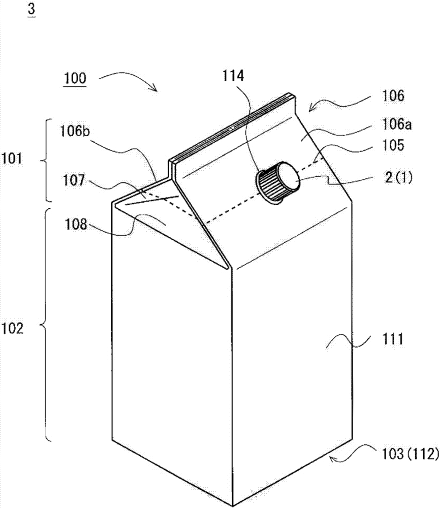
[0057] figure 1 A perspective view of the packaging container 3 is shown. The packaging container 3 has a container main body 100 formed by bending a blank 110 obtained by processing a sheet material 200 described later into a box shape, overlapping and sealing the ends, and a spout plug 1 . The outlet plug 1 has a cap 2 as an example. The container main body 100 includes: a top 101, which becomes the upper part when standing upright; a cylindrical part 102, which becomes the side; and a bottom 103, which becomes the lower part. The fold-in plate 107 and the fold-back plate 108 between the roof panels 106 . A circular spout hole 114 is formed in the roof plate 106a. The outlet plug 1 is installed in the outlet hole 114 . On the top portion 101 , as an example, a weak portion 105 that weakens the br...
Deformed example 2
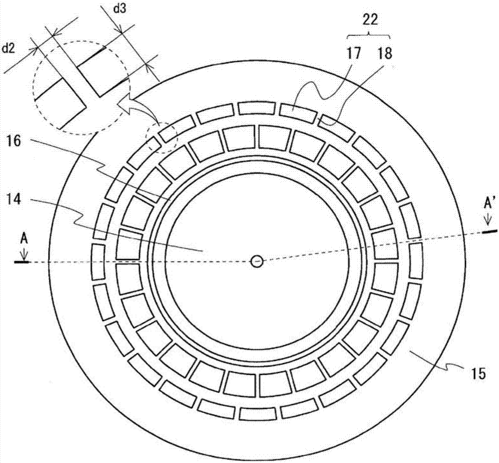
[0068] Figure 3B In the shown sprue plug, a plurality of ribs 182 are formed in addition to the ribs 181. The ribs 182 are directed from the inside of the flange 15 toward the outside when viewed on the plane of the flange 15, with respect to the lid. 2. The direction opposite to the direction of rotation at the time of screwing extends at an inclination of a second predetermined angle smaller than a right angle. The second predetermined angle is, for example, 60°. As a result, the ribs 182 have a honeycomb structure in which the triangular recesses 17 are arranged in a circumferential shape, so that the flange portion 15 can increase rigidity against loads from directions parallel to the plane including the flange portion 15 .
[0069]
[0070] Figure 4 A plan view of a blank 110 which is an example of a blank to be a material of the container body 100 is shown. The blank 110 has: roof panels 106a, 106b, fold-in panels 107, and fold-back panels 108, which form the top ...
no. 2 Embodiment approach
[0095] A second embodiment of the present invention will be described.
[0096]
[0097] Figure 7 A perspective view of the packaging container 3 is shown. The packaging container 3 has a container main body 100 formed by bending a blank 110 processed from a sheet described later into a box shape, overlapping and sealing the ends, and a spout plug 1 . The outlet plug 1 has a cap 2 as an example. The container main body 100 includes: a top 101, which becomes the upper part when standing upright; a cylindrical part 102, which becomes the side; and a bottom 103, which becomes the lower part. The fold-in plate 107 and the fold-back plate 108 between the roof panels 106 . A circular spout hole 114 is formed in the roof plate 106a. The outlet plug 1 is installed in the outlet hole 114 .
[0098]
[0099] Figure 8 A plan view of a blank 110 which is an example of a blank to be a material of the container body 100 is shown. The blank 110 has: roof panels 106a, 106b, fold-...
PUM
 Abstract
Description
Claims
Application Information