Steel storage device

A type steel and loading technology, which is applied in the direction of object stacking, loading/unloading, transportation and packaging, etc., can solve the problems of complex device structure, large equipment scale, and increased cost, so as to improve operation efficiency and facilitate operation sequence , cost reduction effect

Inactive Publication Date: 2018-11-09
NISSHIN STEEL CO LTD
View PDF12 Cites 0 Cited by
  • Summary
  • Abstract
  • Description
  • Claims
  • Application Information

AI Technical Summary

Problems solved by technology

However, the existing storage devices have problems in that not only the structure of the entire device is complicated, but also the scale of the equipment is large, which increases the cost and requires a large space.

Method used


Image

  • Steel storage device
  • Steel storage device
  • Steel storage device

Examples


Embodiment

[0048] Hereinafter, examples of the present invention will be described, but the present invention is not limited to the following examples, and can be implemented with appropriate changes within the scope of the gist of the invention.

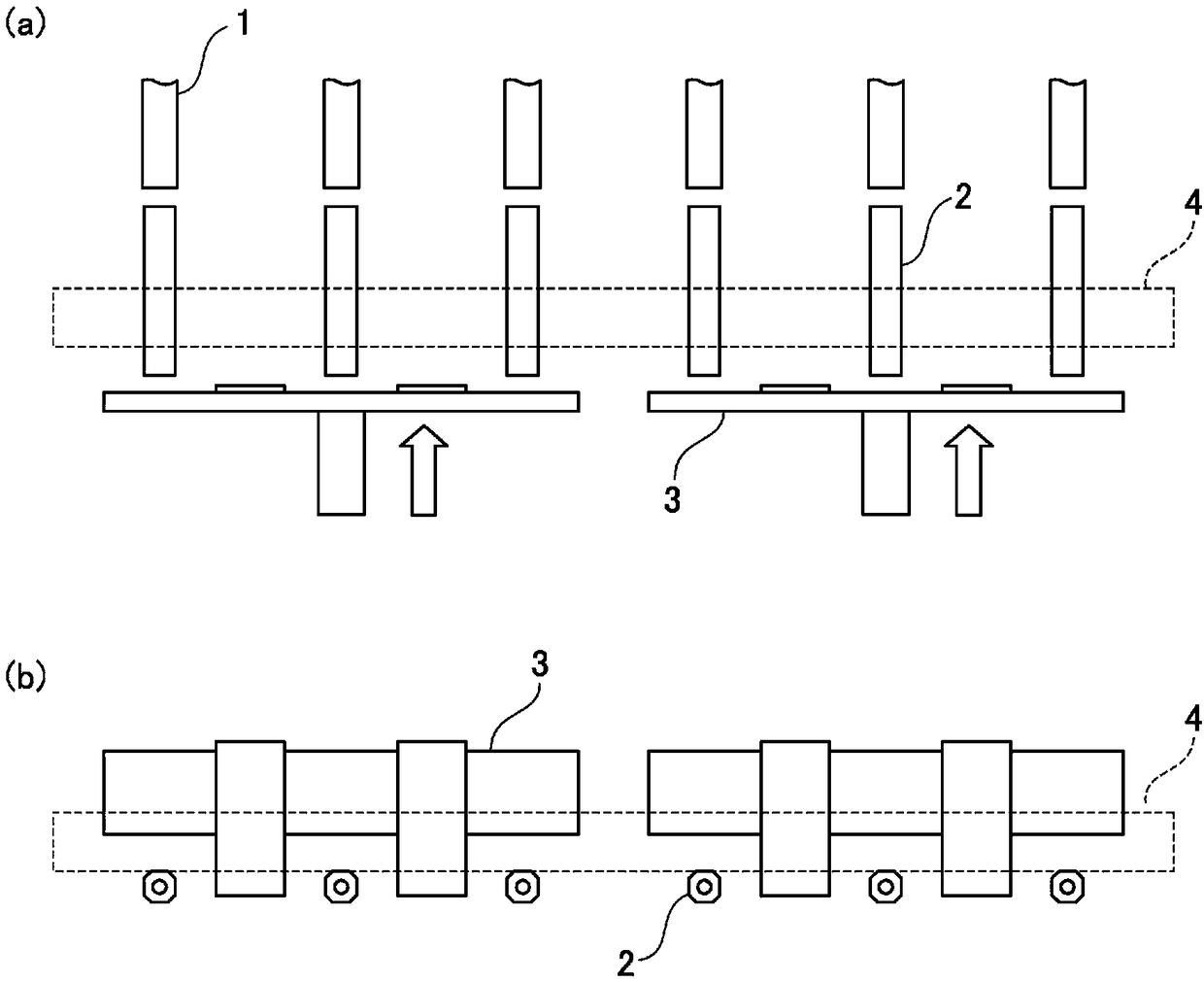
[0049] figure 1 A specific example of the storage device of the present invention is shown. Shown is the equipment provided with two stacking devices, the stacking device is equipped with three rotating belts (stacking platform 1), stacking rollers (conveying platform 2), and a pusher (extrusion mechanism 3). ). The pusher is provided with a plate-shaped member that can pass between the transfer tables. The H-shaped steel 4 is carried in from the storage place (not shown) to the transfer table 2, straddles the transfer table 2 of the two storage devices, and stands by.

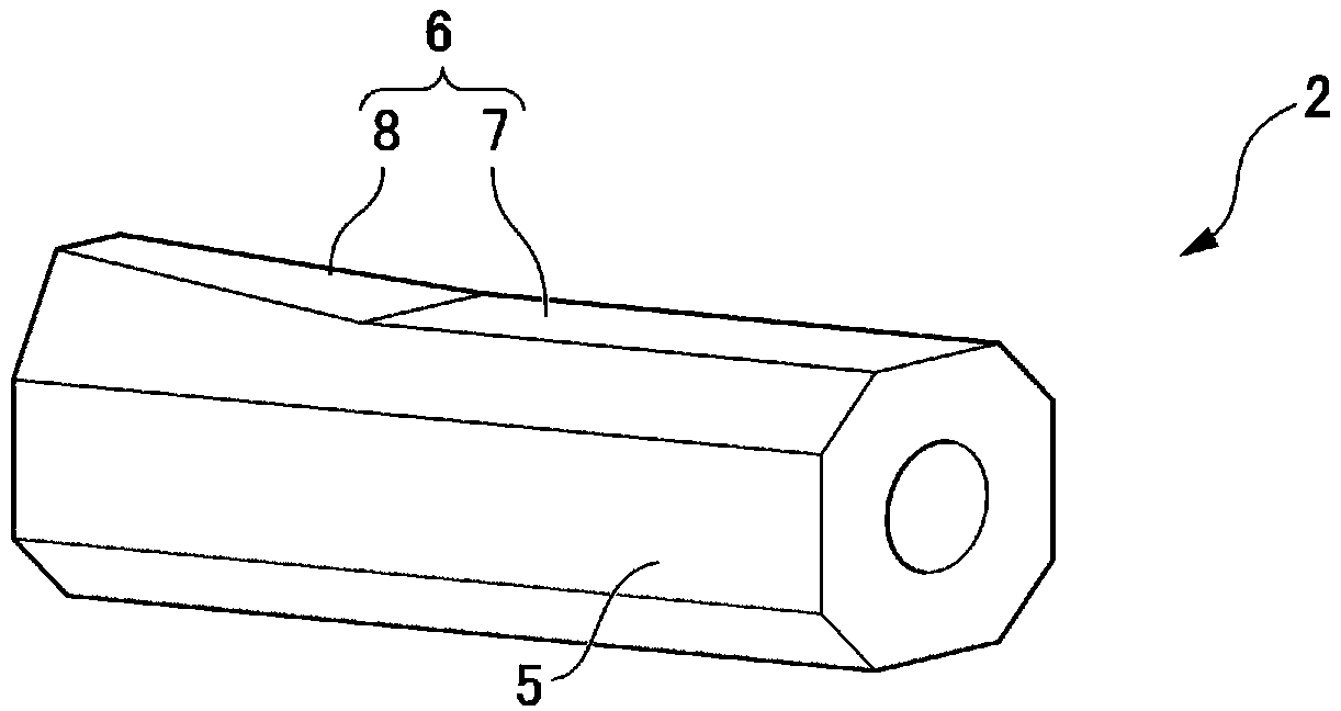
[0050] figure 2 It is a schematic diagram which shows the specific example of the transfer table 2 of this invention. The transfer table 2 has a prism shape having a cr...


PUM


Abstract

The present invention provides a stacking device for stacking shaped steel with a small-scale facility using a transfer mechanism having a simple structure. The present invention comprises: a stacking platform (1) for placing stacked shaped steels (4); a plurality of loading surfaces (5, 6) of the transfer table (2); and a push-out mechanism (3) that pushes out the section steel (4) placed on the above-mentioned transfer table (2) to the above-mentioned stacking table, and the above-mentioned transfer table (2) includes: A first loading surface (5); and a second loading surface (6) having a flat portion (7) and an inclined portion (8), the above-mentioned inclined portion (8) is formed opposite to the above-mentioned stacking platform (1) On one side, the above-mentioned first and second loading surfaces (5, 6) can be selected according to the order in which the above-mentioned shaped steel (4) is pushed out.

Description

technical field [0001] The present invention relates to a stacking device for stacking a plurality of section steels. Background technique [0002] When storing a plurality of H-shaped steels, a device (storage device) for stacking a plurality of H-shaped steels by alternately stacking flange portions of the H-shaped steels is used. The existing storage device arranges a plurality of H-shaped steels on the same surface, and then moves the H-shaped steels arranged in even-numbered rows among them in the vertical direction. Then, other H-shaped steels are pushed in laterally, and the flanges of these H-shaped steels are stacked alternately, thereby stacking a plurality of H-shaped steels. When moving the above-mentioned even-numbered H-shaped steel, a mechanism that pushes up from below and a mechanism that lifts up from above are used. In addition, when moving, the mechanism which moves H-beams one by one, or the mechanism which moves a plurality of them at the same time is...

Claims


Application Information

Patent Timeline
Patent Type & Authority Patents(China)
IPC IPC(8): B65G57/18B65G57/09
CPCB65G57/09B65G57/18B65G57/10B65G2814/0304B65G2201/0214
Inventor 樱田康弘朝田博家成彻松泽胜康
Owner NISSHIN STEEL CO LTD
Why Eureka
Try Eureka