Automatic transmission of a vehicle, comprising a central synchronizing device, and method for operating an automatic transmission
A technology of automatic transmission and synchronous device, applied in the direction of brakes, transmission devices, vehicle components, etc., can solve the problems of impaired driving comfort, high operating cost, and high operating cost
- Summary
- Abstract
- Description
- Claims
- Application Information
AI Technical Summary
Problems solved by technology
Method used
Image
Examples
Embodiment Construction
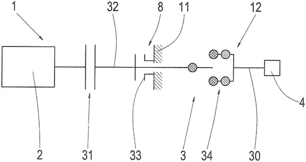
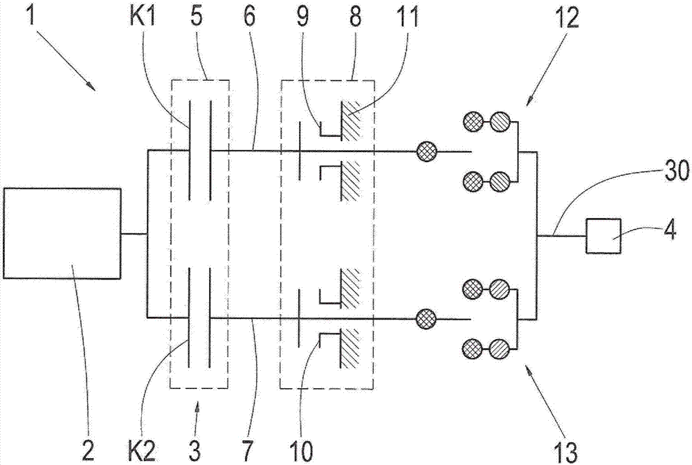
[0047] figure 1 A vehicle drive train 1 is shown with a drive machine 2 , an automatic transmission 3 and an output 4 . On the transmission input side, the drive machine 2 can be coupled via a clutch device 31 to a transmission input shaft 32 in a known manner. Assigned to the transmission input shaft 32 is a central synchronizer 8 , which here includes a shifting element 33 designed as a friction brake. In this case, torque can be transmitted or supported between the transmission input shaft 6 and the transmission housing 11 in the region of the brake 33 . Between the brake 33 and the output 4 , which is connected to the transmission output shaft 30 , there is a transmission range 34 , via which transmission range it is possible to engage and deactivate a form-locking shifting element, for example a dog shifting element. Engage and disengage each of the different gear ratios.
[0048] Depending on the requirements respectively present for operating the vehicle drive train ...
PUM
 Abstract
Description
Claims
Application Information
 - R&D
- Intellectual Property
- Life Sciences
- Materials
- Tech Scout
- Unparalleled Data Quality
- Higher Quality Content
- 60% Fewer Hallucinations
Browse by: Latest US Patents, China's latest patents, Technical Efficacy Thesaurus, Application Domain, Technology Topic, Popular Technical Reports.
© 2025 PatSnap. All rights reserved.Legal|Privacy policy|Modern Slavery Act Transparency Statement|Sitemap|About US| Contact US: help@patsnap.com


