cooling fan

A cooling fan and fan technology, applied in the fields of heating and fan cooling, can solve the problem of consuming water in the water tank, and achieve the effects of uniform cooling and heating, ensuring cooling, and excellent cooling effect.

Inactive Publication Date: 2019-12-24
杭州帝赐科技有限公司
View PDF11 Cites 1 Cited by
  • Summary
  • Abstract
  • Description
  • Claims
  • Application Information

AI Technical Summary

Problems solved by technology

[0006] The purpose of the present invention is to provide a cooling fan, which solves the problem of continuous consumption of water in the water tank when the cooling fan is cooling, and has the advantages of excellent cooling effect, humidification, small limitations, and convenient use

Method used


Image

  • cooling fan
  • cooling fan
  • cooling fan

Examples


Embodiment 1

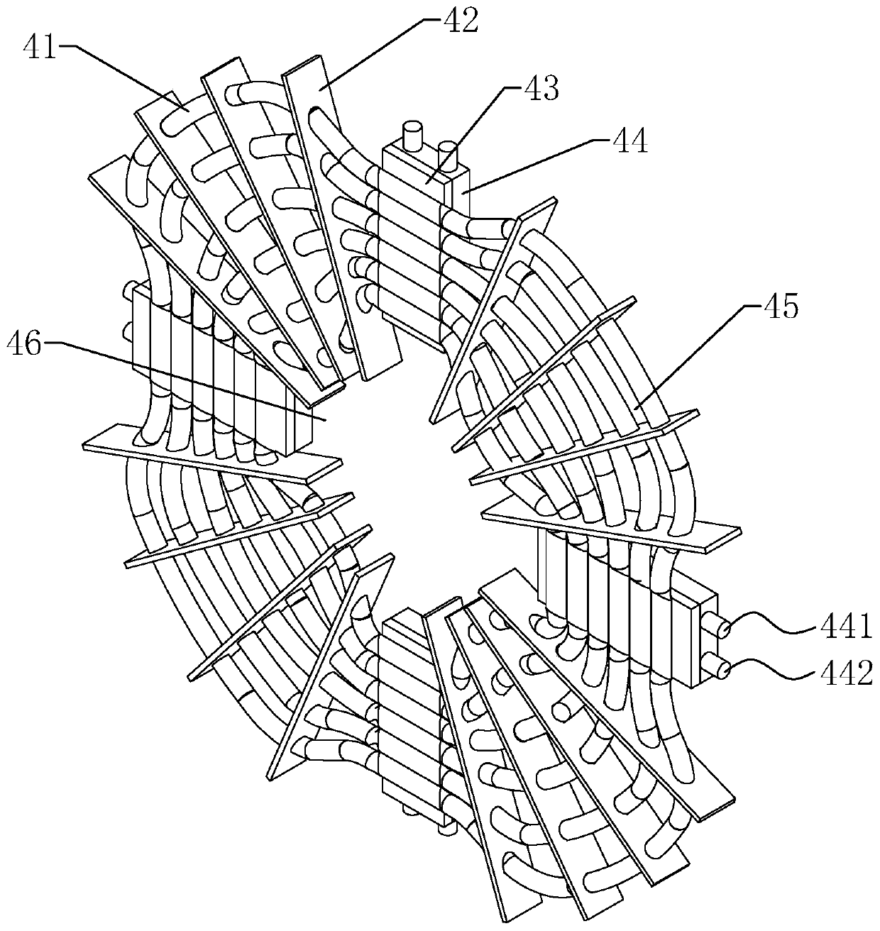
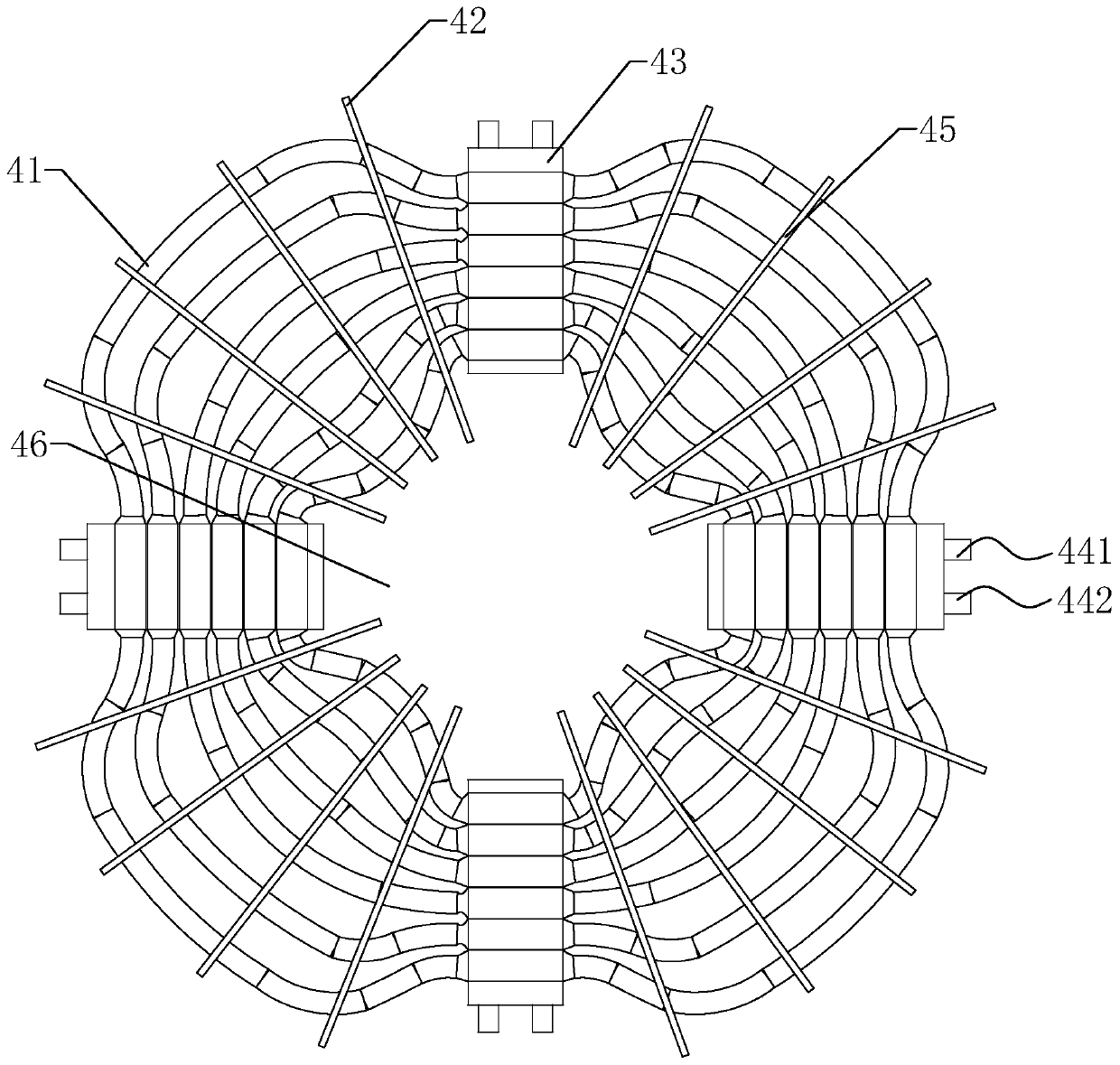
[0057] Embodiment 1: A refrigeration panel 4, such as figure 2 with image 3 As shown, it includes a plurality of thermally conductive copper tubes 41, a plurality of thermally conductive fins 42 and a plurality of first refrigerating fins 43. In this embodiment, the number of thermally conductive copper tubes 41 is six, and the six thermally conductive copper tubes 41 are ring-shaped closed with the same shape. The structure is set on the same plane and is gradually enlarged.

[0058] A ventilation gap is provided between two adjacent heat-conducting copper pipes 41, the cold surface of the first cooling sheet 43 is attached to the heat-conducting copper pipe 41, and the part where the heat-conducting copper pipe 41 is attached to the cold surface is flat to increase the contact area. In addition, the ventilation gap between two adjacent first cooling fins 43 is gradually enlarged toward the middle of the two first cooling fins 43, so as to avoid a large gap between the heat con...

Embodiment 2

[0063] Example 2: Such as Figure 5 As shown, the difference from Embodiment 1 is that the first water block 44 in this embodiment is provided with a communication channel 446 and a number of partition plates 445. The partition plate 445 divides the interior of the water block into multiple cavities. The communication channel 446 penetrates the partition plate 445 from the middle of the partition plate 445 to divide the partition plate 445 into two parts, and communicates with the cavity between the partition plates 445. The inlet 441 and the outlet 442 of the first water cooling head 44 are respectively arranged along the edge The two outermost cavities in the direction of the communication passage 446. The cold water enters from the inlet 441 and fills the first water block 44 through the communication channel 446. At this time, when cold water continues to enter from the inlet 441, water pressure is generated to send the water in the first water block 44 from the outlet 442. ...

Embodiment 3

[0065] Example 3: Such as Image 6 As shown, the difference from embodiment 1 or 2 is that the heat-conducting fin 42 in this embodiment is arc-shaped and forms a spiral structure on the refrigeration panel 4, wherein the heat-conducting fin 42 is inclined toward the end of the spiral curve. , The spiral direction of the spiral structure is the same as the rotation direction of the electric fan 5. Through the spiral structure and the inclined heat conduction fins 42 are arranged, the air passing through the heat conduction fins is spiraled, and the air is mixed to achieve the effect that the temperature and humidity of the blown air are more uniform.


PUM


Abstract

The invention discloses a refrigerating fan. The refrigerating fan comprises an electric fan, a refrigerating device and a humidifying device, the electric fan comprises a blowing end and a negative pressure end, the refrigerating device comprises a water tank and a refrigerating panel with ventilating openings, the refrigerating panel is located on the negative pressure end of the electric fan and is provided with a plurality of first refrigerating sheets and first water cooling heads attaching to the hot faces of the first refrigerating sheets, the cold faces of the first refrigerating sheets attach to the refrigerating panel, the water tank and the first water cooling heads is connected through a water channel circulation pipeline, and a water receiving disc used for receiving condensed water on the refrigerating panel and sending the condensed water to the humidifying device is arranged below the refrigerating panel. The problem that water in the water tank needs to be consumed continuously during refrigerating of the refrigerating fan is solved, and the refrigerating fan has the advantages of being good in refrigerating effect, capable of realizing humidifying effect, small in limitation and convenient to use.

Description

Technical field [0001] The invention relates to the technical field of fan cooling and heating, in particular to a cooling fan. Background technique [0002] Fan refers to an appliance fan used to generate wind and cool in hot weather. It is a device that generates airflow with electricity. The fan inside is energized and then turns into natural wind to achieve the effect of cooling off. However, with the development of society, the demand for fans for cooling or heating is also increasing. [0003] Existing patents, such as the Chinese patent with patent announcement number CN102620363B and application announcement date on October 29, 2014, disclose an evaporation and electronic dual refrigeration cooling fan, which includes a box with an air inlet and an air outlet, and is placed in the box The electronic refrigeration system, evaporative refrigeration system and electric wind wheel in the body. Among them, the electronic refrigeration system includes: an electronic refrigerati...

Claims


Application Information

Patent Timeline
Patent Type & Authority Patents(China)
IPC IPC(8): F24F5/00F24F6/16
CPCF24F5/0042F24F6/16Y02B30/54
Inventor 茅金冲
Owner 杭州帝赐科技有限公司
Why Eureka
Try Eureka