Implanted energy collection device

An energy harvesting and device technology, applied in the field of implantable energy harvesting devices, can solve the problems of unfavorable generator contact separation, reducing generator output, etc.

Active Publication Date: 2017-12-05
BEIJING INST OF NANOENERGY & NANOSYST
View PDF4 Cites 6 Cited by
  • Summary
  • Abstract
  • Description
  • Claims
  • Application Information

AI Technical Summary

Problems solved by technology

The less gas sealed during packaging, the weaker the extrusion on the packaging layer will be, and the stability of the generator will be improved. However, due to the decrease of the internal ai

Method used


Image

  • Implanted energy collection device
  • Implanted energy collection device
  • Implanted energy collection device

Examples


Embodiment 1

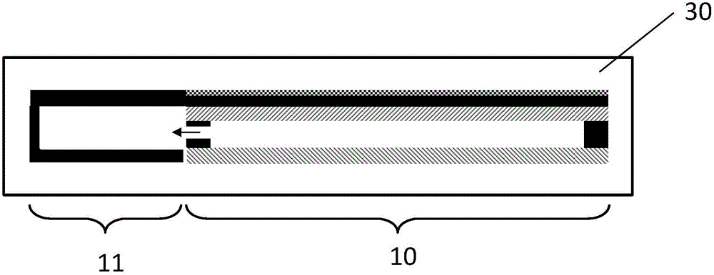
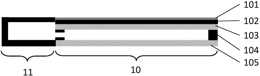
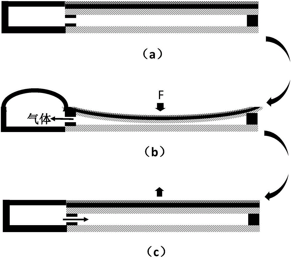
[0046] see figure 1 , the typical structure of the implantable energy harvesting device provided in this embodiment includes a triboelectric nanogenerator 10 and a buffer airbag 11, the buffer airbag 11 is arranged at one end of the triboelectric nanogenerator 10, and the two are encapsulated in the encapsulation layer 30, Among them, the friction nanogenerator 10 has two power generation parts that can be separated from each other. Gas is encapsulated between the two power generation parts. The buffer airbag 11 is an elastically stretchable airbag structure. Stomata or gas passages are connected.

[0047] The buffer airbag 11 is made of elastic materials, such as polymer materials such as rubber, silicone, and resin, or other natural or synthetic materials with high elasticity.

[0048] The size of the buffer airbag 11 is adapted to the friction nanogenerator 10, and its height and width should not exceed the height and width of the friction nanogenerator 10 because it is lo...

Embodiment 2

[0058] see Figure 4 , the typical structure of the implantable energy harvesting device provided in this embodiment includes a triboelectric nanogenerator 20 and a buffer airbag 21, the buffer airbag 21 is arranged under the triboelectric nanogenerator 20, and the two are encapsulated in the encapsulation layer 30, Wherein, the frictional nanogenerator 20 has two power generation parts that can be separated from each other, and gas is encapsulated between the two power generation parts, and the buffer airbag 21 is an elastically stretchable airbag structure. Stomata or gas passages are connected.

[0059] The difference from the first embodiment lies in that the positions of the air holes or gas passages for gas flow in this embodiment are different.

[0060] In this embodiment, the structure of the triboelectric nanogenerator 20 can be all existing triboelectric nanogenerators. Its typical structure is to have two power generation parts that can contact and separate each ot...


PUM


Abstract

The invention provides an implanted energy collection device. A buffer air bag is arranged on a packaged friction nanometer power generator, comprises an elastic telescopic structure and is connected with a space between two friction layers of the friction nanometer power generator via an air hole or an independently-designed gas passage; when the fiction layers of the friction nanometer power generator are in contact with each other by an effect of an external force, a gas between the two friction layers enters the buffer air bag to be temporarily stored via the air hole or the gas passage; and when the external force is removed, the temporarily-stored gas can be automatically discharged to the space between the two friction layers by the buffer air bag, and the fiction layers are helped to complete separation action. With the energy collection device structure provided by the invention, contact and separation can be effectively completed by the friction nanometer power generator to achieve normal output performance, a direct effect of an internal gas on a package layer is also prevented, and the stability of the device is improved.

Description

technical field [0001] The invention relates to the field of implantable devices, in particular to an implantable device for collecting energy. Background technique [0002] In recent years, implantable pulse generators (such as cardiac pacemakers, brain pacemakers, etc.) challenge. [0003] Nanogenerators can use the phenomenon of electron transfer that occurs when materials with different positions in the triboelectricity series contact and / or rub against each other. Nanogenerators have the characteristics of flexibility, small size, and light weight. They can convert energy generated by biomechanical movements inside and outside the human body into electrical energy, and are very suitable for driving implantable, portable, and small self-propelled electronic devices. [0004] When the implantable triboelectric nanogenerator is implanted in the body, flexible packaging is required to ensure the stability of the internal device in the complex environment in the body. Bas...

Claims


Application Information

Patent Timeline
IPC IPC(8): H02N1/04
CPCH02N1/04
Inventor 李舟郑强刘卓金一鸣石波璟邹洋欧阳涵王中林
Owner BEIJING INST OF NANOENERGY & NANOSYST
Why Eureka
Try Eureka