Architectural engineering construction on-site protective shed

A construction site and construction engineering technology, applied in the direction of buildings, small buildings, building types, etc., can solve the problems of limited gravity bearing capacity of protective sheds, project losses, and easy breakdown of overhead protection, etc., to achieve sensitive sliding response and structural The damage reduction and the effect of reducing the interaction force

Inactive Publication Date: 2017-08-04
赵吉生
View PDF5 Cites 4 Cited by
  • Summary
  • Abstract
  • Description
  • Claims
  • Application Information

AI Technical Summary

Problems solved by technology

There are many danger sources in the building construction site. The falling of objects is one of the major danger sources in the construction site, and it is also a production safety accident that is very likely to occur in the construction site. It is fatal, and if it is serious, it will also cause economic losses to the project
At present, the on-site construction of fastener-type steel pipe protective sheds is a common way for construction site protective sheds. However, since it is only a temporary facility, the gravity bearing capacity of the entire protective shed is relatively limited. Most of the roofs of the protective sheds only use color steel tiles as Overhead protection, a few with additional layers of formwork added for strength
Obviously, for objects falling from high altitude, such as bricks, steel structure parts, etc., such overhead protection is obviously easy to be penetrated

Method used


Image

  • Architectural engineering construction on-site protective shed
  • Architectural engineering construction on-site protective shed

Examples


Embodiment Construction

[0018] In order to clearly illustrate the technical features of the solution, the solution will be described below through specific implementation modes.

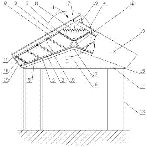
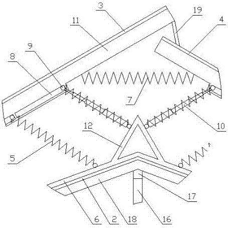
[0019] Such as figure 1 As shown, the present embodiment is a construction site protective shed, including a steel structure support, the steel structure support is provided with an inlet and outlet, the top of the steel structure support is provided with a top protection structure, and the top protection structure includes a structure fixedly connected to the steel structure support. The two-slope top-type fixed protection layer 2, the upper side of the fixed protection layer 2 is provided with an unloading structure 1; the unloading structure 1 includes a movable plate 3 and a movable plate 2 respectively corresponding to the two slopes of the fixed protective layer 2 , the slope of movable plate one 3 and movable plate two 4 is greater than the slope of fixed protection layer 2, and the upper end of movable plate one 3 s...


PUM


Abstract

The invention discloses an architectural engineering construction on-site protective shed which is composed of a basic structure and a force unloading structure. The basic mechanism is composed of a steel structure bracket and a fixed protective layer to form a supporting frame and the most basic head top protection measure; the force unloading structure comprises a first movable plate, a second movable plate and springs which connect the first movable plate and the second movable plate with the fixed protective layer, and thus an energy absorbing structure is formed; in addition, the force unloading structure further comprises long strip holes and sliding rods which are formed/arranged on the lower portions of the first movable plate and the second movable plate; and the stroke of a falling object is enlarged in collision through sliding of the sliding rods along the long strip holes, so that mutual interaction force in collision is reduced. The beneficial effects of the architectural engineering construction on-site protective shed can be known according to detail description of the scheme, the structure is simple, the design is reasonable, when the falling object in the high place falls down, the force unloading structure can dissolve the impact force of the falling object, and the situation that impact force of the falling object penetrates through the top protection is avoided.

Description

technical field [0001] The invention relates to an engineering safety management facility, in particular to a protective shed at a construction site of a construction project. Background technique [0002] The construction site operation is a high-risk production activity, and the mixers produced on the construction site need to be produced under the protective shed. There are many danger sources in the building construction site. The falling of objects is one of the major danger sources in the construction site, and it is also a production safety accident that is very likely to occur in the construction site. It is fatal, and if it is serious, it will also cause economic losses to the project. At present, the on-site construction of fastener-type steel pipe protective sheds is a common way for construction site protective sheds. However, since it is only a temporary facility, the gravity bearing capacity of the entire protective shed is relatively limited. Most of the ro...

Claims


Application Information

Patent Timeline
Patent Type & Authority Applications(China)
IPC IPC(8): E04H1/12E04G21/32
CPCE04G21/3204E04H1/1205
Inventor 丛苏莉张旭升山红政李钦高超
Owner 赵吉生
Why Eureka
Try Eureka