Breather valve applied to breathing machine and control method of breather valve

A breathing valve and ventilator technology, which is applied in the field of medical equipment, can solve the problems of unfavorable gas breathing valve, poor exhaust of breathing valve, and difficulty breathing of patients, so as to achieve the effect of increasing pressure, smooth exhaust and reducing gas leakage

Pending Publication Date: 2017-12-08
王侨
View PDF5 Cites 2 Cited by
  • Summary
  • Abstract
  • Description
  • Claims
  • Application Information

AI Technical Summary

Problems solved by technology

[0003] The breathing valve on the existing membrane-type ventilator, because water vapor will be generated during the breathing process, the water vapor will condense on the membrane, and the membrane will contact the sealed seat ring to generate suction, which is very unfavorable for gas to enter the breathing valve. This will lead to poor breathing, and at the same time, the breathing valve may also have poor exhaust during the exhaust process, thereby increasing the patient's breathing difficulty

Method used


Image

  • Breather valve applied to breathing machine and control method of breather valve
  • Breather valve applied to breathing machine and control method of breather valve
  • Breather valve applied to breathing machine and control method of breather valve

Examples


Embodiment 1

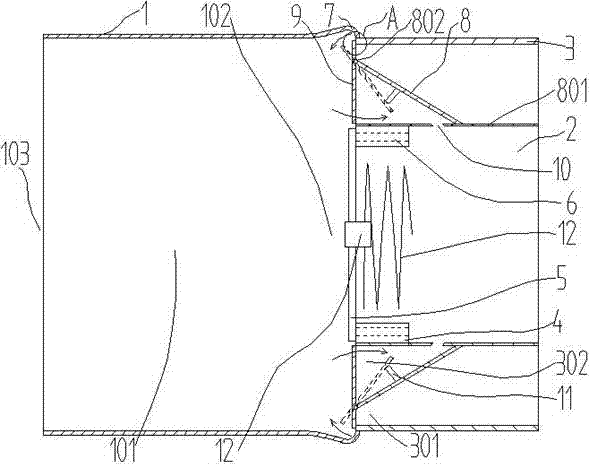
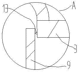
[0030] Such as Figure 1 to Figure 5 The shown breathing valve used on the ventilator includes: a valve body 1 with a rectangular cross section, with a cavity 101 in the valve body 1;

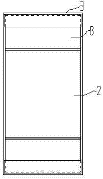
[0031] The intake pipe 2 and the outer pipe 3, the intake pipe 2 and the outer pipe 3 are all arranged on the intake and exhaust end 102 of the valve body 1, the intake and exhaust end 102 is arranged opposite to the breathing end 103, the cross section of the intake pipe 2 is rectangular, and the outer pipe 3 In order to form a rectangular tube on the two opposite surfaces of the intake pipe 2, the inner wall of the exhaust end of the intake pipe 2 is fixedly installed with a seat ring 4, and the end of the seat ring 4 is equipped with a valve that can be opened and closed and restricts the flow of gas from the cavity 101 to the air outlet. The diaphragm 5 flowing in the intake pipe 2 can be made of silicon rubber, and the middle part of the diaphragm 5 is fixedly installed on a pillar, and th...

Embodiment 2

[0038] On the basis of Embodiment 1, add the following technical features: as Figure 1~6 As shown, a solenoid valve 14 is provided in the communication hole 10, and the middle part of the valve body 1 is provided with a temperature sensor a and an air flow detector b respectively. Connection, the processor, the solenoid valve 14, the temperature sensor and the airflow direction detector are respectively adapted to be equipped with power supplies.

[0039] The method for controlling the breathing valve used on the ventilator is characterized in that it comprises the following steps:

[0040] 1) There is oxygen in the intake pipe, the pressure in the valve body 1 is lower than the pressure in the intake pipe 2 when inhaling, the temperature sensor measures the temperature in the valve body, when the temperature is too low, the processor controls the spiral heating coil 12 to The set power works, when the temperature is at a normal value, the processor controls the spiral heati...


PUM


Abstract

The invention discloses a breather valve applied to breathing machines and a control method of the breather valve. The breather valve comprises a valve body, an air inlet tube and an outer tube, the air inlet tube and the outer tube are arranged at air inlet and exhaust ends of the valve body, the outer tube is a rectangular tube formed on two opposite sides of the air inlet tube, a seat ring is fixedly installed on the inner wall of the exhaust end of the air inlet tube, a membrane is installed at one end of the seat ring, vent holes are formed in the seat ring, a partition plate extending outwards to the entry to the outer tube and gradually increasing in distance with the air inlet tube is formed on the outer periphery of the air inlet tube, two opposite sides of the partition plate, located at the entry to the outer tube and the orifice of the outer tube are parallel, the partition plates divides the outer tube into an outer air path away from the air inlet tube and an inner air path close to the air inlet tube, a communicating hole used for communicating the inner air path with the air inlet tube is formed in the tube wall of the air inlet tube, and the free end of the partition plate is rotatably provided with a sealing plate. By the arrangement, smoothness in breathing can be improved by the aid of the breather valve.

Description

technical field [0001] The invention belongs to the field of medical equipment, in particular to a breathing valve used in a ventilator and a method for controlling it. Background technique [0002] Ventilators are often used during the treatment and rehabilitation of patients. Ventilators are vital medical equipment to prevent and treat respiratory failure, reduce complications, and save and prolong the lives of patients. The breathing valve in the ventilator is its key equipment. [0003] The breathing valve on the existing membrane-type ventilator, because water vapor will be generated during the breathing process, the water vapor will condense on the membrane, and the membrane will contact the sealed seat ring to generate suction, which is very unfavorable for gas to enter the breathing valve. As a result, poor breathing may occur, and the problem of poor exhaust may also occur during the exhaust process of the breathing valve, thereby increasing the patient's breathing...

Claims


Application Information

Patent Timeline
Patent Type & Authority Applications(China)
IPC IPC(8): A61M16/20
CPCA61M16/0003A61M16/201A61M2205/3331A61M2205/3368A61M2205/36
Inventor 王侨
Owner 王侨
Why Eureka
Try Eureka