Viscous fluid discharging device

A technology of viscous liquid and equipment, applied in the field of viscous liquid discharge equipment

Active Publication Date: 2017-12-08
TOP ENG CO LTD
View PDF17 Cites 4 Cited by
  • Summary
  • Abstract
  • Description
  • Claims
  • Application Information

AI Technical Summary

Problems solved by technology

[0008] Fluctuations in delivery pressure on the outlet side of the liquid supply hole 3 change the discharge volume at the nozzle 5, which causes problems in precise control of the discharge volume

Method used


Image

  • Viscous fluid discharging device
  • Viscous fluid discharging device
  • Viscous fluid discharging device

Examples


Embodiment Construction

[0031] Hereinafter, exemplary embodiments of the present invention will be described in detail with reference to the accompanying drawings. First of all, when referring to reference numerals of constituent elements of respective drawings, it should be understood that the same constituent elements will be referred to by the same reference numerals even if shown in different drawings. Further, in the following description of the present invention, when it is considered that detailed descriptions of publicly known configurations or functions included herein may make the object of the present invention unclear, the detailed descriptions will be omitted. Further, although the exemplary embodiments of the present invention are described below, the technical spirit of the present invention is not limited thereto, and those skilled in the art can implement it with improvements and changes.

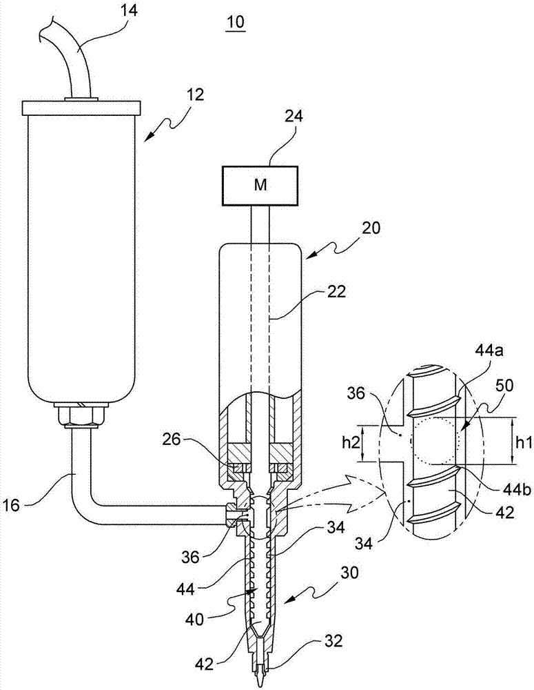
[0032] image 3 The view of shows the viscous liquid discharge apparatus according to the fir...


PUM


Abstract

The invention relates to a viscous fluid discharging device which can discharge fluid with viscousity through accurately controlling the discharging amount of the fluid. The viscous fluid discharging device provided by the invention comprises the components of a syringe which stores and supplies the viscous fluid; a nozzle body which comprises a fluid supplying hole that is formed at the side surface and is supplied with the viscous fluid by the syringe, a screw insertion hole which is formed therein, and a nozzle for discharging the viscous fluid; and a discharging screw which is inserted into the screw insertion hole and rotates for conveying the viscous fluid that is supplied by the fluid supplying hole, wherein the discharging screw comprises a screw shaft and a spiral edge which is formed on the outer circumferential surface of the screw shaft, and a no-edge part which is not provided with the spiral edge is arranged at one part of the screw shaft, wherein the part corresponds with the forming position of the fluid supplying hole.

Description

technical field [0001] The present invention relates to a viscous liquid discharge device. More particularly, the present invention relates to a viscous liquid discharge device capable of discharging viscous liquid by precisely controlling the liquid discharge amount. Background technique [0002] In a process of manufacturing an electronic device such as a flat panel display or a semiconductor package, a process of attaching a member or a process of filling a member with a fluid is performed. [0003] For example, a flat panel display (FPD) such as a liquid crystal display (LCD) and an organic light emitting diode (OLED) display is manufactured by bonding two flat panels together. To hold the two plates together, a viscous liquid called a paste or sealant is dispensed onto either plate through a dispenser. As an example, Korean Patent No. 1115916 (registration date: February 7, 2012) of the present applicant discloses a paste dispenser and a control method for dispensing ...

Claims


Application Information

Patent Timeline
Patent Type & Authority Applications(China)
IPC IPC(8): B05B9/047B05B12/08
CPCB05B9/047B05B12/085B05C5/02B05C5/0254G02F1/1303H10K50/8426
Inventor 李浩济李光渊池恩赫
Owner TOP ENG CO LTD
Why Eureka
Try Eureka