Supercharge Your Innovation With Domain-Expert AI Agents!

Clamp for clamping cutting tool

A technology for clamping tools and clamps, applied in clamps, manufacturing tools and other directions, can solve the problems of labor and inconvenience, and achieve the effect of simple structure and convenient operation

Inactive Publication Date: 2017-12-08
姚前华
View PDF10 Cites 2 Cited by
  • Summary
  • Abstract
  • Description
  • Claims
  • Application Information

AI Technical Summary

Problems solved by technology

[0002] In the process of mechanical processing and manufacturing, in order to ensure production safety, the use, clamping, and replacement of tools in machine tools require the use of clamps to take, clamp, and replace tools; when traditional clamps clamp tools, It is very inconvenient to separate the two handles of the furniture by hand, especially when using new or rusty clamps to clamp the knife, it will be very laborious

Method used


Image

  • Clamp for clamping cutting tool
  • Clamp for clamping cutting tool
  • Clamp for clamping cutting tool

Examples


Embodiment Construction

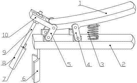
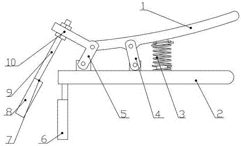
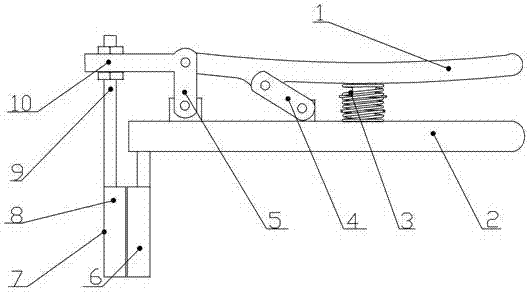
[0012] The present invention will be described in further detail below in conjunction with the accompanying drawings.

[0013] Such as figure 1 , figure 2 A clamp for clamping tools according to the present invention includes clamp arm one 1, clamp arm two 2, splint one 6, splint two 7; the clamp arm one 1 is located above the clamp arm two 2, and Between arm one 1 and pincer arm two 2, connecting plate one 5, connecting plate two 4, and spring 3 are successively installed from back to front. The tail end of 2 is vertically fixed with a suspension plate 10 on the connection plate one 5, and the suspension plate 10 can rotate with the rotation of the connection plate one 5; and the middle rear part of the pincer arm two 2; the two ends of the spring 3 are respectively fixed on the lower surface of the pincer arm one 1 and the upper surface of the pincer arm two 2; the splint one 6 is vertically fixed on the lower surface end of the pincer arm two 2 part; the splint two 7 is...


PUM


Abstract

The invention relates to the field of clamps and clamping tools, in particular to a clamp for clamping a cutting tool. The clamp comprises a first clamp arm, a second clamp arm, a first clamping plate and a second clamping plate; the first clamp arm is located above the second clamp arm, a first connection plate, a second connection plate and a spring are arranged between the first clamp arm and the second clamp arm in sequence from back to front, two ends of the first connection plate are hinged to tail ends of the firs clamp arm and the second clamp arm respectively, and a hung plate is vertically fixed onto the first connection plate; two ends of the second connection plate are hinged to the middle back portions of the first clamp arm and the second clamp arm respectively; two ends of the spring are fixed to the lower surface of the first clamp arm and the upper surface of the second clamp arm respectively; the first clamping plate is vertically fixed to the end of the lower surface of the second clamp arm; the second clamping plate is composed of a bolt and a groove plate, the upper end of the bolt is connected to the hung plate in a threaded mode and fixed to the hung through an upper nut and a lower nut, and the lower end of the bolt is fixed to the top of the groove plate. The clamp for clamping the cutting tool is simple in structure and convenient to operate, a handle can be automatically separated, and a double leverage structure is adopted, so that the labor is saved when the cutting tool is clamped.

Description

technical field [0001] The invention relates to the field of pliers and clamping tools, in particular to a pliers for clamping tools. Background technique [0002] In the process of mechanical processing and manufacturing, in order to ensure production safety, the use, clamping, and replacement of tools in machine tools require the use of clamps to take, clamp, and replace tools; when traditional clamps clamp tools, It is very inconvenient to separate the two handles of the furniture by hand for clamping, especially when using new or rusty clamps for cutting tools, it will be very laborious. Contents of the invention [0003] In view of the above problems, the object of the present invention is to provide a clamp for clamping tools with simple structure, convenient operation, automatic separation of handles, and effortless clamping of tools. [0004] A clamp for clamping tools, comprising clamp arm one, clamp arm two, splint one, splint two; the clamp arm one is located a...

Claims


Application Information

Patent Timeline
IPC IPC(8): B25B5/04
CPCB25B5/04
Inventor 姚前华
Owner 姚前华
Features
  • R&D
  • Intellectual Property
  • Life Sciences
  • Materials
  • Tech Scout
  • Unparalleled Data Quality
  • Higher Quality Content
  • 60% Fewer Hallucinations
Learn More