Heating device of drainage plate in muffle furnace and control method of heating device

A technology of a heating device and a control method, which is applied in the direction of manufacturing tools, glass molding, glass molding, etc., and can solve problems such as the limited effect of increasing the temperature of the drainage plate, the difficulty of further increasing the temperature of the drainage plate, and the limited means of raising the temperature of the drainage plate. , to achieve the effects of reducing heat loss, simple structure, stability and consistency

Active Publication Date: 2017-12-08
RAINBOW (HEFEI) LIQUID CRYSTAL GLASS CO LTD
View PDF5 Cites 6 Cited by
  • Summary
  • Abstract
  • Description
  • Claims
  • Application Information

AI Technical Summary

Problems solved by technology

First of all, the heater of the muffle furnace is relatively far away from the diversion plate, the heat radiation distance is relatively large, the heat radiation efficiency is low, and the effect on raising the temperature of the diversion plate is limited
Secondly, considering the greater the insertion depth of the upper plywood mechanism in the forming area, the higher the risk of sticking
In actual production, the insertion depth of the plywood must ensure that it has a certain safety distance from the molten glass flowing down from the drainage plate, thus reducing the thermal insulation effect of the plywood mechanism on the area where the drainage plate is located, making it difficult to further increase the temperature of the drainage plate
[0006] To sum up, the existing technology has limited means to increase the temperature of the drainage plate, and cannot well suppress the crystallization

Method used


Image

  • Heating device of drainage plate in muffle furnace and control method of heating device
  • Heating device of drainage plate in muffle furnace and control method of heating device
  • Heating device of drainage plate in muffle furnace and control method of heating device

Examples


Embodiment Construction

[0039] The present invention will be further described in detail below in conjunction with specific embodiments, which are explanations of the present invention rather than limitations.

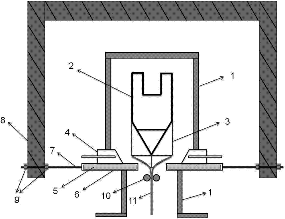
[0040] Such as figure 1As shown, under the soaking effect of the soaking hood 1, the molten glass has a certain viscosity, and is filled and evenly overflowed at the overflow tank 2, passes through the drainage plate 3, and is finally pulled down by the traction mechanism 10. A monolithic glass ribbon 11 is formed. Considering the decreasing distribution of the temperature field in the muffle furnace, and the use of the blower box 4 to adjust the thickness, the heat will be dissipated, resulting in a lower temperature at the diversion plate 3, and the molten glass may crystallize on the diversion plate 3 . In order to suppress crystallization of the molten glass on the diversion plate 3 , it is necessary to increase the temperature of the diversion plate 3 , which can be achieved by setting...


PUM


Abstract

The invention discloses a heating device of a drainage plate in a muffle furnace and a control method of the heating device. The device comprises a soaking cover, a drainage plate and two heaters which are arranged in the muffle furnace as well as a horizontal adjusting mechanism arranged on the muffle furnace, wherein the drainage plate is arranged in the soaking cover; the two heaters are positioned at a junction of the muffle furnace and a moulding area and are arranged on the side wall of the soaking cover respectively and are in sealing contact with the side wall of the soaking cover; the two heaters are symmetrically arranged on the two sides of the drainage plate; the horizontal adjusting mechanism is used for adjusting the horizontal inserting depths of the heaters. An aim of increasing temperature of the drainage plate is achieved by designing and producing an inserting type heater to replace an original upper plywood mechanism in the moulding area and adjusting the inserting depth and power (or current) of the heater, thus the crystallization of molten glass on the drainage plate is inhibited, the stability and consistency of the moulding quality of a glass substrate are further improved, and the service life of the muffle furnace is prolonged to a great degree.

Description

technical field [0001] The invention belongs to the field of overflow down-draw flat glass manufacturing, and in particular relates to a heating device for a diversion plate in a muffle furnace and a control method thereof. Background technique [0002] The overflow down-draw method is one of the main methods for the production of liquid crystal glass substrates. This method is to send molten glass with a suitable viscosity into the overflow tank. Since the two ends of the overflow tank are provided with Platinum baffle device, when the overflow tank is full, the molten glass will overflow to the inclined wall along both sides of the overflow tank, and under the guidance of the diversion plate, the two streams of glass liquid will merge to form a glass root, which will be drawn through the bottom The downward pull of the mechanism forms a thin ribbon of monolithic glass. The outstanding advantage of this method is that the glass surface is not in contact with any material, ...

Claims


Application Information

Patent Timeline
Patent Type & Authority Applications(China)
IPC IPC(8): C03B17/06
CPCC03B17/064
Inventor 陆兵兵李文军
Owner RAINBOW (HEFEI) LIQUID CRYSTAL GLASS CO LTD
Why Eureka
Try Eureka