Core engine and turbine engine

A core engine and turbine technology, applied in the direction of machine/engine, engine components, mechanical equipment, etc., can solve the problems of large amount of cold air, unavoidable, and lower engine thermal efficiency.

Inactive Publication Date: 2017-12-08
AECC COMML AIRCRAFT ENGINE CO LTD
View PDF5 Cites 3 Cited by
  • Summary
  • Abstract
  • Description
  • Claims
  • Application Information

AI Technical Summary

Problems solved by technology

[0005] 1. It is unavoidable to bleed air from the final stage of the high-pressure compressor, which reduces the thermal efficiency of the engine;
[0006] 2. The cold air temperature of the bleed air from the final stage of the high-pressure compressor is relatively high, and the required amount of cold air is large, which further reduces the thermal efficiency of the engine

Method used


Image

  • Core engine and turbine engine
  • Core engine and turbine engine
  • Core engine and turbine engine

Examples


Embodiment Construction

[0024] The technical solutions of the present invention will be described in further detail below with reference to the accompanying drawings and embodiments.

[0025] The specific embodiments of the present invention are for the convenience of further description of the concept of the present invention, the technical problems to be solved, the technical features constituting the technical solution and the technical effects brought about. It should be noted that the description of these embodiments does not constitute a limitation of the present invention. In addition, the technical features involved in the following embodiments of the present invention may be combined with each other as long as they do not conflict with each other.

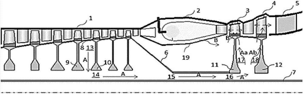
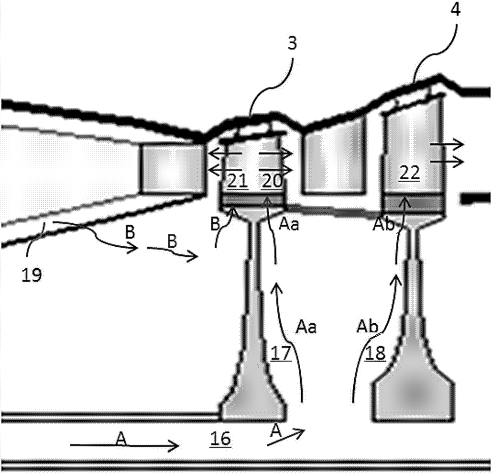
[0026] Aiming at the fact that the cooling of the final stage of the existing turbine engine will reduce the thermal efficiency of the engine, the present invention designs a core machine, which is used for the turbine by bleed air from two diffe...


PUM


Abstract

The invention relates to a core engine and a turbine engine. The turbine engine comprises a gas compressor, a combustion chamber and a turbine; the turbine comprises a turbine first-grade movable blade; the turbine first-grade movable blade is provided with a front cooling cavity near the combustion chamber, and a back cooling cavity far from the combustion chamber; and the front cooling cavity and the back cooling cavity are independently arranged. The core engine further comprises a first cooling flow way and a second cooling flow way; the first cooling flow way can lead final-stage compressed gas of the gas compressor into the front cooling cavity; and the second cooling flow way can lead non-final-stage compressed gas of the gas compressor into the back cooling cavity. The core engine respectively leads the gas from two different positions of the gas compressor for cooling the turbine first-grade movable blade; the final-stage compressed gas and the non-final-stage compressed gas are used for cooling the turbine first-grade movable blade; the total flow needed by cold gas of the turbine first-grade movable blade is totally reduced; the heat efficiency of the engine is improved; and the oil consumption rate is reduced.

Description

technical field [0001] The invention relates to the technical field of turbine engines, in particular to a core engine and a turbine engine. Background technique [0002] In order to improve the thermal efficiency of the civil aviation turbofan engine and reduce the fuel consumption rate, the temperature of the front inlet of the turbine is continuously increased, which brings about the problem that the cooling air required by the high-temperature components is also increased, especially the two-stage turbine. [0003] At present, the cold air of the first-stage moving blade of the two-stage turbine adopts the bleed air from the last stage of the high-pressure compressor, enters the first-stage moving blade after passing through the pre-rotating nozzle, and finally flows from The holes or slits in the front cavity and trailing edge of the first-stage moving blade discharge into the main flow channel. [0004] The existing traditional air supply and blade cooling design meth...

Claims


Application Information

Patent Timeline
IPC IPC(8): F01D5/18
Inventor 陈潇王代军
Owner AECC COMML AIRCRAFT ENGINE CO LTD
Why Eureka
Try Eureka