

Synchronizer slide block and synchronizer and vehicle
A synchronizer and slider technology, applied in clutches, mechanical drive clutches, mechanical equipment, etc., can solve the problems of reducing shifting quality, shifting discomfort, large synchronizing impulse, etc., reducing shifting time, improving shifting Block quality, reduce the effect of secondary impact
- Summary
- Abstract
- Description
- Claims
- Application Information
AI Technical Summary
Problems solved by technology
Method used
Image

Examples
Embodiment 1
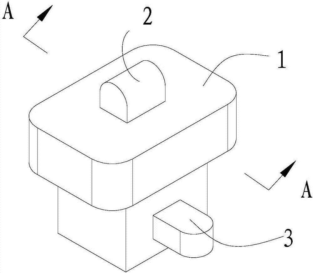
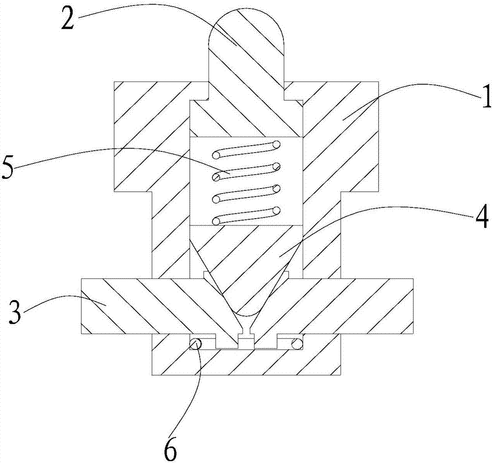
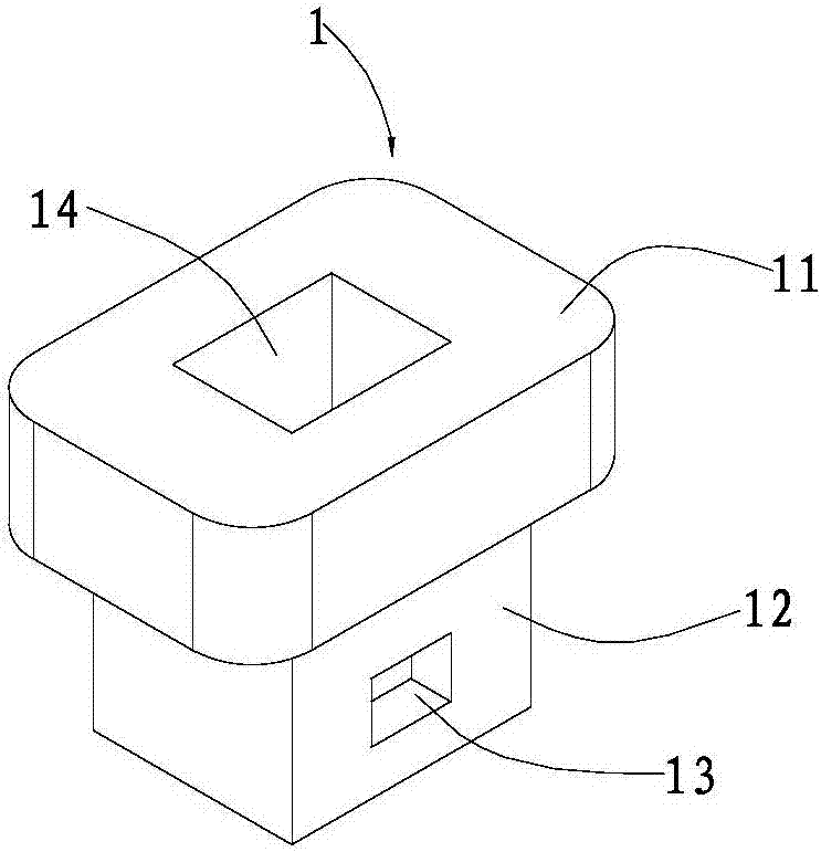
[0033] The invention relates to a slider for a synchronizer, which includes a slider body embedded on the outer peripheral surface of the gear hub and capable of sliding along the axial direction of the gear hub. The protruding power bearing part and the push part slidingly arranged in the slider body along the synchronous direction of the slider body; The transmission part between the pusher part and the push part. When the power bearing part receives an external force and retracts in the slider body, the transmission part can drive the push part due to the drive of the power bearing part. The push part protrudes from the slider body.
[0034] When the slider of the synchronizer is synchronizing, when the power bearing part retracts in the slider body due to the radial pressure of the adapter sleeve, the driving part can drive the push part to protrude in the slider body through the transmission part, so that the slider The main body and the pushing part jointly crimp the sy...
Embodiment 2
[0042] This embodiment relates to a synchronizer, which includes a gear hub, a synchronizing ring located on one side of the gear hub, a coupling tooth, and an adapter sleeve fitted on the gear hub. slider.
[0043] At the same time, this embodiment also relates to a vehicle, which is equipped with the above-mentioned synchronizer.
[0044] The synchronizer and the vehicle of this embodiment can increase the synchronous torque of the synchronous ring during synchronization by using the synchronizer slider in the first embodiment, so as to reduce the shifting time, reduce the synchronous impulse, and improve the shifting quality. Moreover, after the engaging sleeve enters the synchronizing ring, the rotational speed difference between the engaging sleeve and the idle gear at the input end during shifting can also be reduced, reducing the occurrence probability of secondary impact and having a better use effect.
PUM
 Abstract
Description
Claims
Application Information