Clutch capable of being triggered at high speed in uncontrollable manner and maintaining low speed

A clutch and low-speed technology, applied in the clutch field, can solve the problems of clutch energy consumption, complex structure, high cost, etc., and achieve the effects of avoiding rigid impact, good maintainability, and simple structure

Inactive Publication Date: 2017-12-08
上海熠优电梯安全科技有限公司
View PDF14 Cites 6 Cited by
  • Summary
  • Abstract
  • Description
  • Claims
  • Application Information

AI Technical Summary

Problems solved by technology

[0003] However, the existing mechanical, pneumatic, hydraulic, electromagnetic, magneto-rheological and other clutches have complex structures and high costs, especially require additional actuators, and after the daily or clutch trigger work, the clutch needs to be powered. supply; this makes this type of clutch consume energy daily and is not economical, or needs energy protection in place for emergency work but is not reliable
For the existing centrifugal clutches that can work without energy supply, they all require the input shaft to work stably at high speeds. However, after the input shaft speed decreases, they will generally be automatically disconnected. This feature will make the damping device The connection with the elevator transmission system is intermittent, which reduces the reliability of the system and makes it difficult to guarantee the safety of the elevator system during emergency operation

Method used


Image

  • Clutch capable of being triggered at high speed in uncontrollable manner and maintaining low speed
  • Clutch capable of being triggered at high speed in uncontrollable manner and maintaining low speed
  • Clutch capable of being triggered at high speed in uncontrollable manner and maintaining low speed

Examples


Embodiment Construction

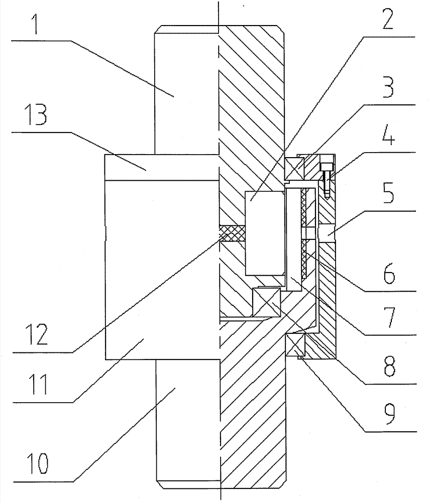
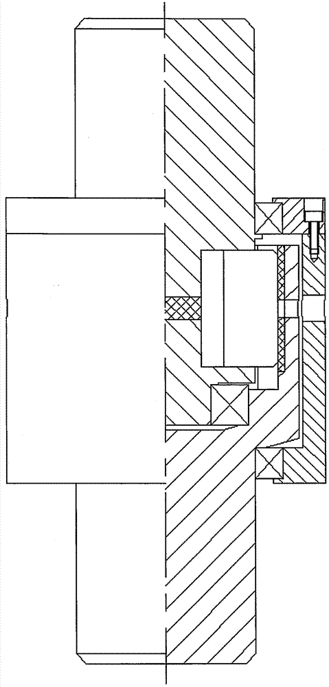
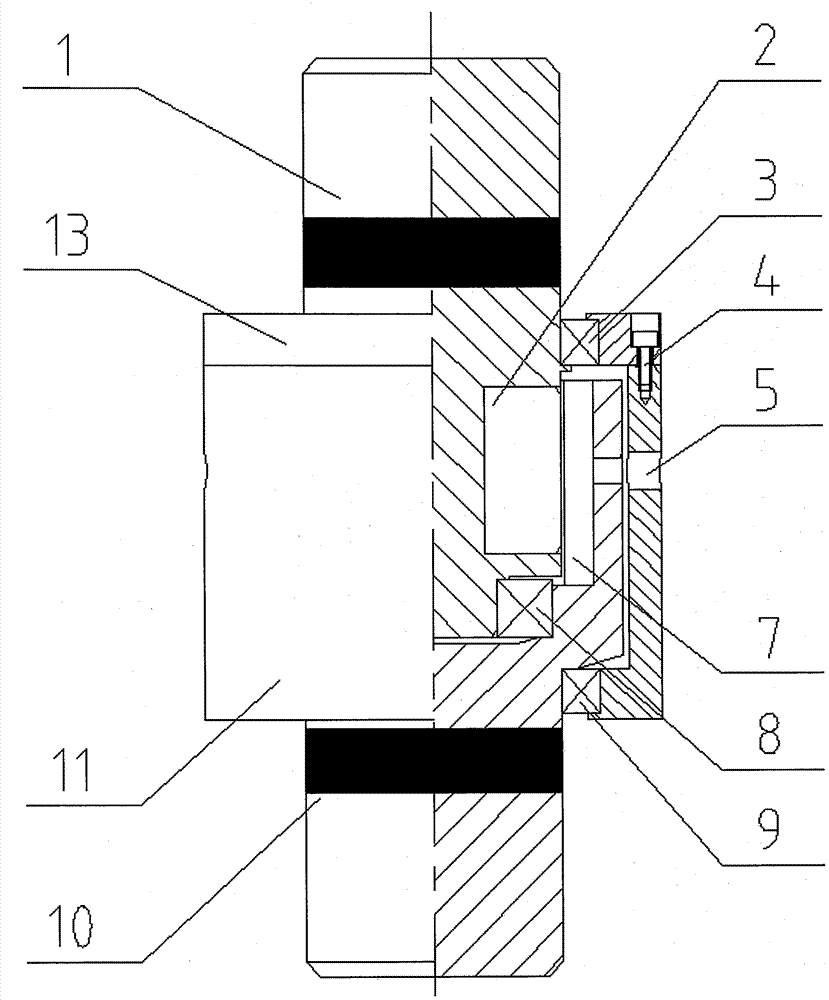
[0020] The invention will be described in more detail hereinafter with reference to the accompanying drawings showing embodiments of the invention. However, this invention may be embodied in many different forms and should not be construed as limited to the embodiments set forth herein. Rather, the embodiments are presented so that this disclosure will be thorough and complete, and will fully convey the invention to those skilled in the art. In the drawings, the size and relative sizes of layers and regions may be exaggerated for clarity.

[0021] In a specific embodiment, the centrifugal card 2 is assembled on the input shaft 1 by means of magnetic force, and when the rotational speed of the input shaft 1 is higher than the set value, the centrifugal card 2 moves to the outer circumference and enters the slot of the output shaft 10 7. Realize the connection between the input shaft 1 and the output shaft 10; the centrifugal block 2 is held in the slot 7 of the output shaft 10...


PUM


Abstract

The invention provides a clutch capable of being triggered at a high speed in an uncontrollable manner and maintaining a low speed. The clutch mainly comprises an input shaft, an output shaft and a centrifugal clamping block. According to the clutch, under the circumstance without supply and control of external energy, the clutch can also work normally. When the input shaft operates at overspeed, the output shaft and the input shaft are connected automatically, transmission is stable, and large torque can be transferred. Particularly after connecting is completed, when the rotating speed of the input shaft is reduced to the low speed from the high speed and even rotating stops, the stable connection maintaining state can still be achieved. The clutch has the beneficial effects of being simple in structure, high in reliability, good in maintainability, low in cost and the like.

Description

technical field [0001] The invention relates to the mechanical field, in particular to a clutch for realizing the transmission of rotational motion of two rotating shafts. Background technique [0002] With the increase in the number of high-rise buildings, the number of traction elevators has increased rapidly, but the problem of evacuation of people in high-rise buildings in emergencies such as fires has become increasingly prominent. The ZL201210346849.5 "an elevator with self-running lifesaving function in case of power failure" has been published, and it is proposed to realize the speed limit operation of the car by connecting the damping device through the clutch, which can also simultaneously solve the problem of accidental stalling and falling of the car s solution. In the above usage scenarios, the functional performance requirements for the clutch are as follows: when the external power supply of the elevator system is interrupted and the elevator transmission sys...

Claims


Application Information

Patent Timeline
Patent Type & Authority Applications(China)
IPC IPC(8): F16D43/16F16D47/02
CPCF16D43/16F16D47/02F16D2043/145
Inventor 汤树人赵克顺赵静
Owner 上海熠优电梯安全科技有限公司
Why Eureka
Try Eureka