Low-temperature up-mounting type fixed ball valve

A fixed ball valve, mounted technology, applied in the direction of valve device, cock including cut-off device, engine components, etc., can solve the problems of large moving space of the spring energy storage seal 50, unfavorable life, and large wear of the spring energy storage seal. , to achieve the effect of convenient disassembly and labor saving, prolonging service life and improving sealing effect

Inactive Publication Date: 2017-12-08
SANBORA VALVE
View PDF6 Cites 1 Cited by
  • Summary
  • Abstract
  • Description
  • Claims
  • Application Information

AI Technical Summary

Problems solved by technology

[0002] see figure 1 As mentioned above, the traditional top entry trunnion ball valve includes a ball, a valve seat, a valve body 20 and a preload nut 60. The valve seat is arranged between the ball and the valve body. The valve seat includes a retainer 30 and a spring seat 40. The valve body 20 There is a spring energy storage sealing ring 50 between it and the fixed seat 30; the traditional top-mounted fixed ball valve has a relatively large left and right axial movement distance h due to assembly requirements. After the ball sealing ring is tightly fitted by the pretightening nut, the spring energy storage The moving space H of the seal ring 50 is large, and the spring energy storage seal ring 50 is pushed by pressure for an excessively long stroke, which will cause increased wear on the sealing surface of the valve body to the spring energy storage seal ring, which is not conducive to its life.

Method used


Image

  • Low-temperature up-mounting type fixed ball valve
  • Low-temperature up-mounting type fixed ball valve

Examples


Embodiment Construction

[0016] In order to make the technical means, creative features, goals and effects achieved by the present invention easy to understand, the present invention will be further described below in conjunction with specific illustrations.

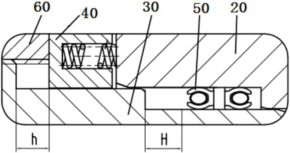
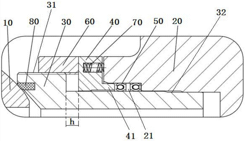
[0017] see figure 2 As mentioned above, the present invention discloses a low-temperature top entry fixed ball valve, which includes a ball 10, a valve seat and a valve body 20, the valve seat is arranged between the ball 10 and the valve body 20, and the valve seat includes two parts: a retainer 30 and a spring seat 40, And the two are split structures, the fixer 30 and the spring seat 40 are screwed and connected through thread fit; the fixer 30 includes a convex end 31 and a concave end 32, the convex end 31 is in contact with the sphere 10, and the concave end 32 is from left to right A spring seat 40 and a valve body 20 are provided in turn, a sealing groove 21 is provided between the bottom of the valve body 20 and the upper surface of th...


PUM


Abstract

The invention discloses a low-temperature up-mounting type fixed ball valve. The low-temperature up-mounting type fixed ball valve comprises a ball body, a valve seat and a valve body, wherein the valve seat is arranged between the ball body and the valve body; the valve seat comprises a fixator and a spring base, which are of split type structures; the fixator comprises a convex end and a concave end, wherein the convex end is in contact with the ball body; the spring base and the valve body are sequentially arranged on the concave end from left to right; a sealing slot is formed between the bottom of the valve body and the upper surface of the concave end; a spring energy-storage sealing ring is arranged in the sealing slot; the spring base is of an L-shaped structure; the bottom of the spring base is equipped with a spring base positioning lug boss; the spring base positioning lug boss extends into the sealing slot, and is used for reducing transverse moving space of the spring energy-storage sealing ring; and the ball valve further comprises a pre-tightening nut which is mounted above the convex end, and one end of the pre-tightening nut is connected with the spring base. The low-temperature up-mounting type fixed ball valve is simple in structure, is convenient to mount and dismount, improves the sealing effect of the valve seat and the valve body, and prolongs the service life of the valve seat.

Description

technical field [0001] The invention relates to the field of ball valves, in particular to a low-temperature top entry fixed ball valve. Background technique [0002] see figure 1 As mentioned above, the traditional top entry trunnion ball valve includes a ball, a valve seat, a valve body 20 and a preload nut 60. The valve seat is arranged between the ball and the valve body. The valve seat includes a retainer 30 and a spring seat 40. The valve body 20 There is a spring energy storage sealing ring 50 between it and the fixed seat 30; the traditional top-mounted fixed ball valve has a relatively large left and right axial movement distance h due to assembly requirements. After the ball sealing ring is tightly fitted by the pretightening nut, the spring energy storage The moving space H of the seal ring 50 is large, and the spring energy storage seal ring 50 is pushed by pressure for an excessively long stroke, which will cause the sealing surface of the valve body to increas...

Claims


Application Information

Patent Timeline
Patent Type & Authority Applications(China)
IPC IPC(8): F16K5/20F16K5/06
CPCF16K5/201F16K5/0636
Inventor 王邦捷黄永刚戴文柏贾琦月李玉龙张怡张鹏
Owner SANBORA VALVE
Why Eureka
Try Eureka