Flue gas system and method for increasing inlet flue temperature of scr denitrification device

A denitrification and flue gas technology, applied in the field of flue gas denitrification, can solve the problems of low flue temperature at the inlet of SCR denitrification device, excessive sewage discharge, high failure rate, etc.

Active Publication Date: 2019-05-31
浙江浙能兰溪发电有限责任公司
View PDF4 Cites 0 Cited by
  • Summary
  • Abstract
  • Description
  • Claims
  • Application Information

AI Technical Summary

Problems solved by technology

However, the catalyst used in SCR denitrification technology is only active within a certain temperature range. Under low load conditions, the flue gas temperature at the inlet of the denitrification device may be lower than the normal operating temperature of the catalyst, resulting in the failure of the SCR denitrification system to operate and eventually causing pollution. Environmental issues such as exceeding standards
[0003] Installing the flue gas bypass baffle on the side of the economizer can solve the problem of low flue gas temperature at the inlet of the SCR denitrification device during low load periods, but installing the bypass baffle will not only increase equipment investment and operation and maintenance costs, but also increase the cost of operation and maintenance during normal operation. , the bypass baffle has been subjected to high-temperature flue gas for a long time, and the failure rate is high. Once the adjustment fails, the furnace can only be shut down.

Method used


Image

  • Flue gas system and method for increasing inlet flue temperature of scr denitrification device
  • Flue gas system and method for increasing inlet flue temperature of scr denitrification device
  • Flue gas system and method for increasing inlet flue temperature of scr denitrification device

Examples


Embodiment Construction

[0022] Specific embodiments of the present invention will be described in detail below in conjunction with the accompanying drawings. It should be understood that the specific embodiments described here are only used to illustrate and explain the present invention, and are not intended to limit the present invention.

[0023] A "low load condition" as referred to in this application is an operating condition in which the operating load of the boiler is less than 50% of its full load.

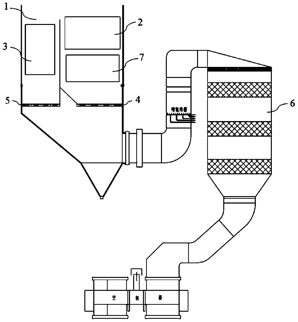
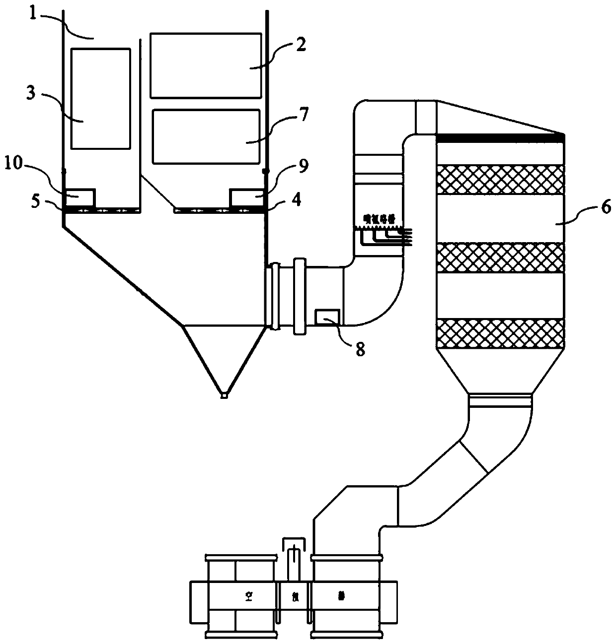
[0024] figure 1 It is a schematic structural diagram of a flue gas system for increasing the inlet flue temperature of an SCR denitrification device according to an embodiment of the present invention. like figure 1 As shown, in one embodiment of the present invention, a flue gas system for increasing the flue gas temperature at the inlet of the SCR denitrification device is provided. The flue gas system may include: a tail flue 1, in which there are arranged side by side For the superheater ...


PUM


Abstract

The invention discloses a flue gas system and method for raising the smoke temperature of an inlet of a SCR denitration device and relates to the technical field of flue gas denitration. The flue gas system comprises a tail smoke channel and the denitration device. A superheater and a reheater are arranged in the tail smoke channel side by side. A superheater side flue gas baffle is arranged below the superheater. A reheater side flue gas baffle is arranged below the reheater. The denitration device communicates with an outlet of the tail smoke channel. The method comprises the step that when a boiler operates in the low-load state, the opening degree of the superheater side flue gas baffle is decreased, and the opening degree of the reheater side flue gas baffle is increased so that flue gas, flowing through the superheater side originally, in the tail smoke channel can be squeezed to the reheater side. By means of the flue gas system and method, the smoke temperature of the inlet of the SCR denitration device is effectively raised; and under the condition that a unit of the same type is not subjected to equipment transformation in any form, the unit can be put into denitration before grid connection.

Description

technical field [0001] The invention relates to the technical field of flue gas denitrification, in particular to a flue gas system and method for increasing the inlet flue temperature of an SCR denitrification device. Background technique [0002] In order to reduce environmental pollution, reducing the emission of nitrogen oxides has become one of the main tasks of power plants. Selective catalytic reduction (SCR) denitrification technology is widely used in power plants due to its high denitrification efficiency and low secondary pollution. However, the catalyst used in SCR denitrification technology is only active within a certain temperature range. Under low load conditions, the flue gas temperature at the inlet of the denitrification device may be lower than the normal operating temperature of the catalyst, resulting in the failure of the SCR denitrification system to operate and eventually causing pollution. Environmental issues such as exceeding standards. [0003] ...

Claims


Application Information

Patent Timeline
Patent Type & Authority Patents(China)
IPC IPC(8): F23J15/08F23L11/00
CPCF23J15/08F23J2900/15081F23L11/00
Inventor 李敏
Owner 浙江浙能兰溪发电有限责任公司
Why Eureka
Try Eureka