
Calculation method of firearm correction amount and gun calibration system

A calculation method and correction amount technology, which is applied in the field of image processing and light weapon shooting research, can solve the problems of slow gun calibration, long time, and inability to calibrate weapons, so as to improve accuracy and reliability, save calculation time, and improve The effect of calibration gun speed

Inactive Publication Date: 2019-05-14
SOUTH CHINA UNIV OF TECH
View PDF7 Cites 0 Cited by
  • Summary
  • Abstract
  • Description
  • Claims
  • Application Information

AI Technical Summary

Problems solved by technology

[0004] The main problem of this method is: for new guns, that is, when the gun barrel and parts are not worn, the error of this method is small, and the method has the advantages of fast calibration of the gun and no need to fire live ammunition.
[0006] 1. The technical level of shooters is extremely high, and ordinary shooters cannot correct their weapons according to their own aiming and shooting habits
Because an ordinary shooter’s gun is unstable during the shooting process, and the trigger is slammed, which will cause deviations in the aiming point, which will affect the position of the impact point, so that the projectile dispersion center calculated by the impact point will have artificial deviations, which will affect the accuracy of the gun calibration and accuracy. reliability
[0007] 2. It takes a long time to manually detect the target and calculate the correction amount, resulting in slow gun calibration and low efficiency. It often takes 5 to 8 minutes or even more time to calibrate a gun
[0008] 3. Higher cost

Method used


Image

  • Calculation method of firearm correction amount and gun calibration system
  • Calculation method of firearm correction amount and gun calibration system
  • Calculation method of firearm correction amount and gun calibration system

Examples


Embodiment 1

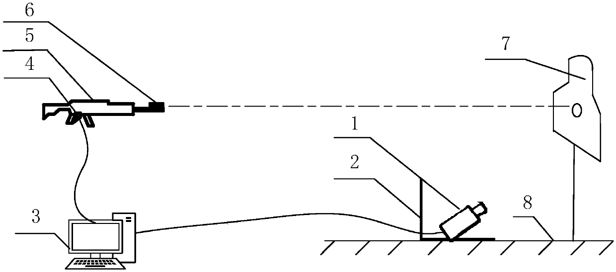
[0040] Such as figure 1 As shown, this embodiment proposes to set up a gun calibration system, including a camera 1 , a camera stand 2 , a host computer 3 , a trigger switch 4 , and a laser transmitter 6 . Wherein the camera 1 is fixed on the camera stand 2, forms an included angle of 25° to 30° with the ground, and is about 2 meters away from the target paper 7, and the target paper 7 is 1.5 meters away from the ground. Camera stand 2 is made up of base plate and protective plate, and base plate is fixed on the ground 8 by fastening nail, is used for keeping camera steady, and protective plate is positioned at camera back and is used for protecting camera from being hit by stray bullet; Base plate and protective plate have The fixed interface of the camera can be moved to adapt to the change of the shooting angle of the camera in different terrains. Laser emitter 6 is fixed on the gun barrel of gun 5, and the laser of launching is parallel with gun barrel, and its trigger sw...


PUM


Abstract

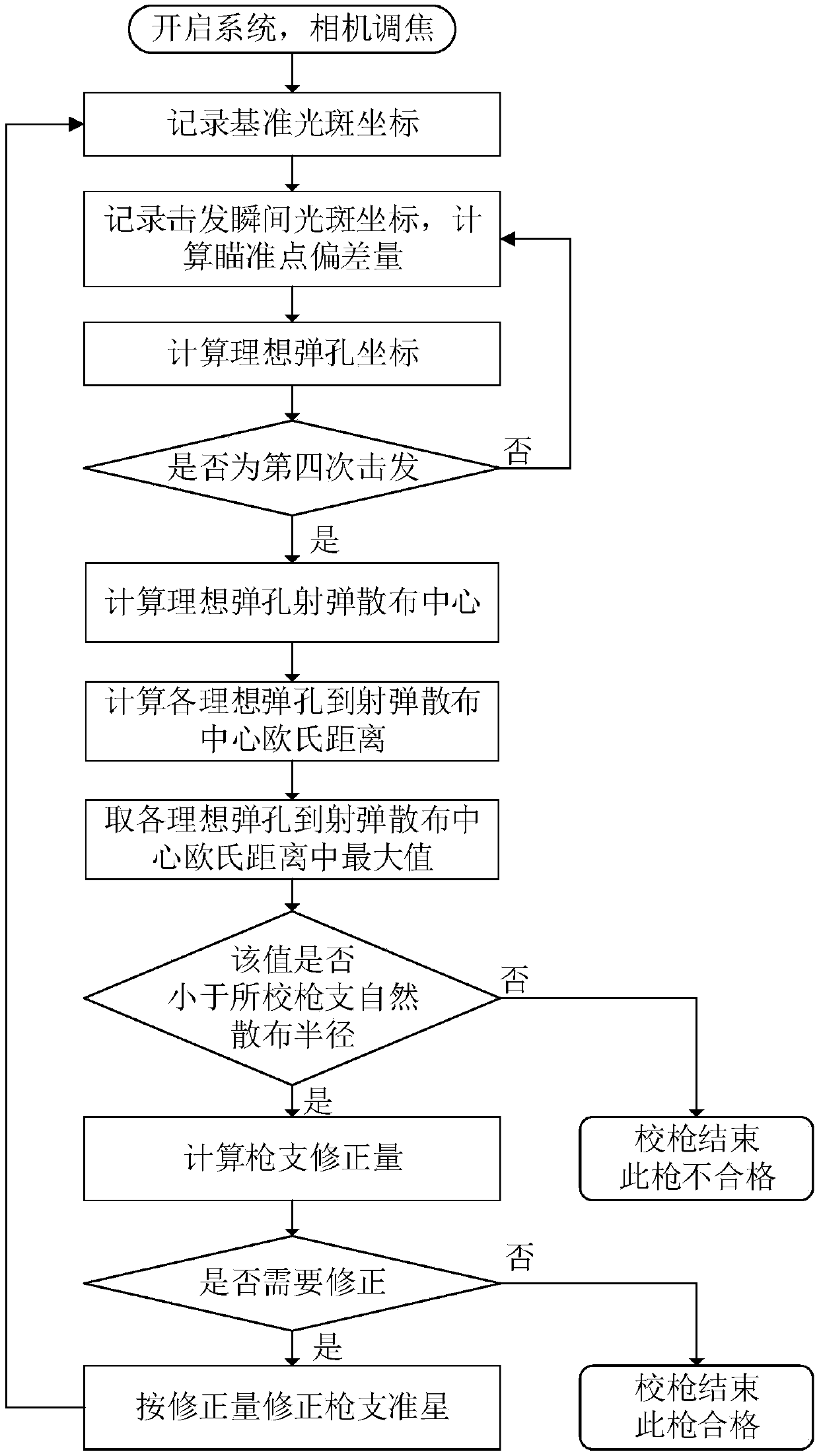
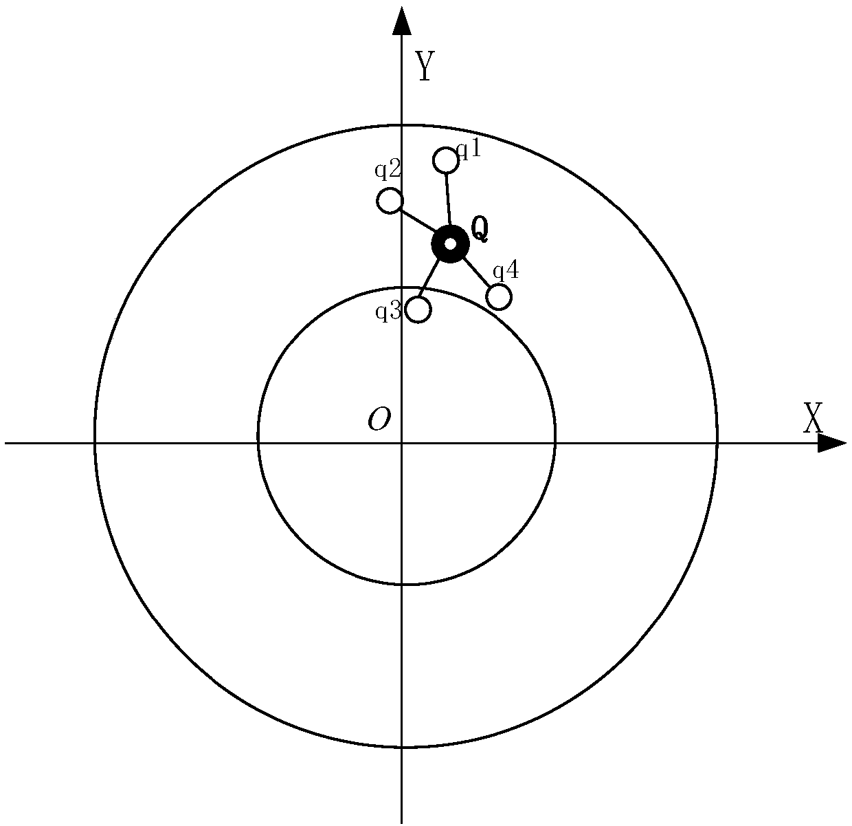
The invention discloses a gun correction calculation method and a gun correcting system thereof. The gun correction calculation method comprises the steps that (1) a laser emitter is fixed to a gun barrel, emitted laser is parallel to the axis of the gun barrel, the laser emitter emits laser to target paper when aiming at a target center, a first image of a target surface is shot, and coordinates of a reference light spot are extracted from the first image; (2) shooting is carried out for N times, triggering moment target surface images and target surface images after the shooting are shot, coordinates of N triggering moment light spots and coordinates of N bullet holes after the shooting are extracted from the triggering moment target surface images and the target surface images after the shooting; (3) through the position changes of triggering moment light spots relative to the reference light spot, aiming point deviation values are calculated; (4) the coordinates of the bullet holes minus the corresponding aiming point deviation values of the bullet holes equal to coordinates of theoretical bullet holes; and (5) a projectile dispersion center of the theoretical bullet holes is calculated, and then a gun correction is calculated. The gun correcting system comprises a camera, a camera seat, an upper computer, a trigger switch, the laser emitter and the like. The speed and the accuracy rate of gun correcting can be raised and the reliability of the gun correcting can be improved.

Description

technical field [0001] The invention relates to the fields of image processing and light weapon shooting research, in particular to a method for calculating a firearm correction amount and a gun calibration system thereof. Background technique [0002] Gun calibration is to adjust the front sight according to the deviation of the projectile for the firearms that do not meet the expected shooting effect. At present, the methods of calibrating guns mainly include two kinds of bulletless laser calibrating guns and live ammunition calibrating guns. [0003] The bulletless laser calibration gun uses the collimation characteristics of the laser to adjust the front sight of the gun. The laser emitter is installed on the barrel and is parallel to the barrel. The specific process is: first obtain the standard spot position, that is, calculate the angle between the barrel and the horizontal plane when the impact point of the firearm is on the bull's eye through the ballistic curve, a...

Claims


Application Information

Patent Timeline
Patent Type & Authority Patents(China)
IPC IPC(8): F41G1/54
CPCF41G1/54
Inventor 罗超群黄茜邓渝波
Owner SOUTH CHINA UNIV OF TECH
Learn More