Malodorous gas detection equipment for organic waste treatment facility

A technology for treating facilities and malodorous gases, which is applied to the analysis of gas mixtures, measuring devices, instruments, etc., can solve the problems of determination, failure to replace manual smell identification, and inability to realize odor concentration and odor intensity, and facilitate installation and removal Effect

Pending Publication Date: 2017-12-08
INST OF GEOGRAPHICAL SCI & NATURAL RESOURCE RES CAS
View PDF5 Cites 1 Cited by
  • Summary
  • Abstract
  • Description
  • Claims
  • Application Information

AI Technical Summary

Problems solved by technology

However, odorous gas will inevitably be produced during the treatment process, and the odor pollution caused by it has become the focus of residents' complaints
Odor pollution is sensory pollution, and its pollution degree is usually evaluated by human sense of smell, but the process of manual smell identification is relatively cumbersome and cannot meet the needs of real-time online monitoring
When using sensors to detect odorous gases, often only the concentration of the corresponding odorous substances in the odorous gas can be given, and the odor concentration and odor intensity cannot be accurately given
There are many malodorous gas detection devices in the prior art, such as the malodorous gas and VOCs monitoring system based on the sensor network can realize the detection of various malodorous substances and VOCs, but cannot realize the determination of odor concentration and odor intensity. Unable to achieve the purpose of replacing artificial smell identification

Method used


Image

  • Malodorous gas detection equipment for organic waste treatment facility
  • Malodorous gas detection equipment for organic waste treatment facility

Examples


Embodiment Construction

[0017] The present invention will be described in further detail below in conjunction with the accompanying drawings and embodiments, but the content described is only a preferred embodiment of the present invention and cannot be considered as limiting the implementation scope of the present invention. All equivalent changes and improvements made according to the application scope of the present invention shall still belong to the scope of the present invention.

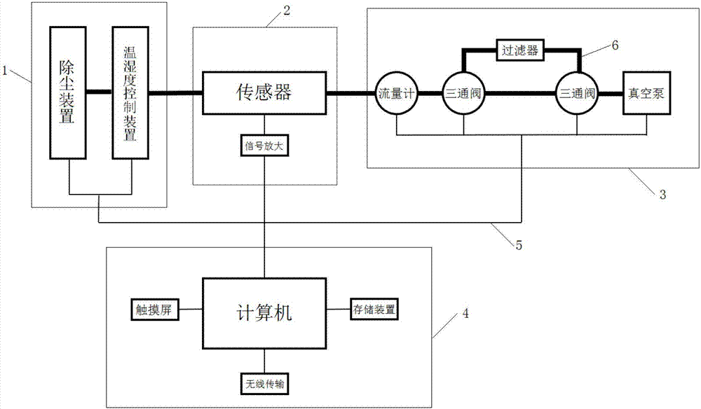
[0018] Such as figure 1 As shown, the present invention provides a malodorous gas detection device for an organic waste treatment facility, which can realize on-line detection of the intensity and concentration of the malodorous gas. The present invention includes a pre-processing module 1 , a sensor module 2 , an air pump module 3 and a signal processing module 4 . The air path between the pre-processing module 1 and the sensor module 2, the sensor module 2 and the air pump module 3 is connected by a polytetrafluor...


PUM


Abstract

The invention relates to malodorous gas detection equipment for an organic waste treatment facility. The detection equipment comprises a pretreatment module, wherein gas circuits between the pretreatment module and a sensor module and between the sensor module and an air pump module are connected by a polytetrafluoroethylene pipe; a signal processing module is connected with the pretreatment module, the sensor module and the air pump module by data lines; the pretreatment module is used for treating detected gases to enable the detected gases to be transmitted to the sensor module after detection conditions of the sensor are met; the sensor module is used for detecting components of the detected gases and transmitting the detected data to the signal processing module by data lines; the air pump module is used for producing a pressure difference, so that the detected gases stably pass through the sensor module; the air pump module is capable of producing odor-free gases so as to perform back-flushing on the sensor module and the pretreatment module; the signal processing module is used for controlling operating states of the pretreatment module and the air pump module, processing the detected data transmitted by the sensor module and calculating the odor concentration and intensity of the gases.

Description

technical field [0001] The invention relates to the field of environmental monitoring, in particular to a detection device for malodorous gas in organic waste treatment facilities. Background technique [0002] With the development of the economy, the output of organic waste in my country is increasing year by year, and the number of various types of organic waste treatment facilities is also increasing. However, malodorous gas will inevitably be produced during the treatment process, and the odor pollution caused by it has become the focus of residents' complaints. Odor pollution is sensory pollution, and its pollution degree is usually evaluated by human sense of smell, but the process of manual smell identification is relatively cumbersome and cannot meet the needs of real-time online monitoring. When a sensor is used to detect malodorous gas, it can only give the concentration of the corresponding malodorous substance in the malodorous gas, and cannot accurately give th...

Claims


Application Information

Patent Timeline
Patent Type & Authority Applications(China)
IPC IPC(8): G01N33/00
CPCG01N33/0004
Inventor 郑国砥邵珠泽陈同斌聂二旗
Owner INST OF GEOGRAPHICAL SCI & NATURAL RESOURCE RES CAS
Why Eureka
Try Eureka