Antenna used for terminal equipment

A terminal equipment and antenna technology, applied in the field of communication, can solve problems such as harsh working environment, large space occupied by dual cameras, and squeezed diversity antenna clearance, etc., to achieve the effect of improving radiation capability and radiation efficiency, and excellent communication capability

Active Publication Date: 2017-12-08
BEIJING XIAOMI MOBILE SOFTWARE CO LTD
View PDF6 Cites 7 Cited by
  • Summary
  • Abstract
  • Description
  • Claims
  • Application Information

AI Technical Summary

Problems solved by technology

However, the dual cameras take up a lot of space, which will squeeze the headroom of the diversity antenna, making its working environment more harsh, and the antenna design faces a huge challenge

Method used


Image

  • Antenna used for terminal equipment
  • Antenna used for terminal equipment
  • Antenna used for terminal equipment

Examples


Embodiment Construction

[0035] The exemplary embodiments will be described in detail here, and examples thereof are shown in the accompanying drawings. When the following description refers to the accompanying drawings, unless otherwise indicated, the same numbers in different drawings represent the same or similar elements. The implementation manners described in the following exemplary embodiments do not represent all implementation manners consistent with the present disclosure. Rather, they are only examples of devices and methods consistent with some aspects of the present disclosure as detailed in the appended claims.

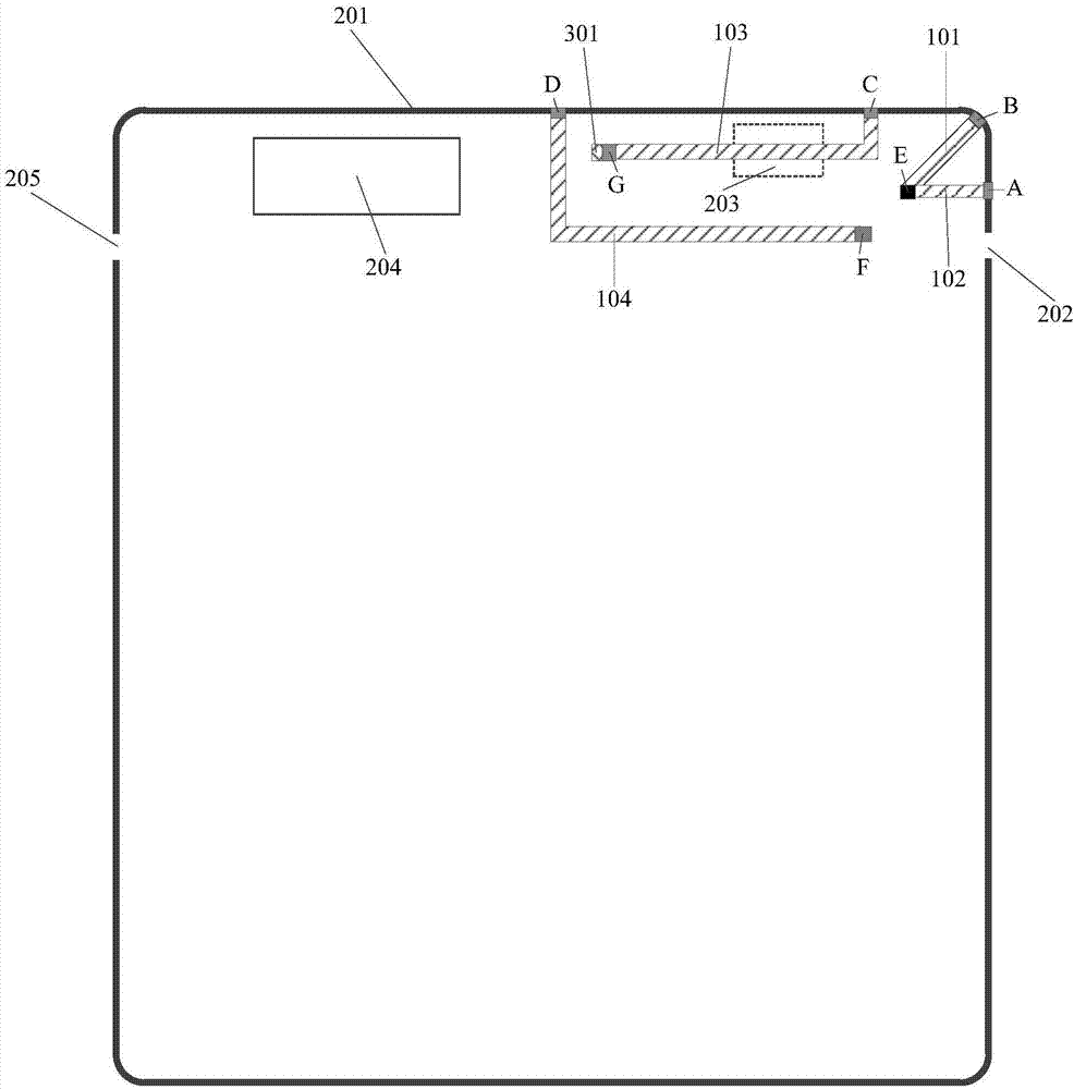
[0036] figure 1 It is a schematic structural diagram showing an antenna for terminal equipment according to an exemplary embodiment. The antenna for terminal equipment can be applied to terminal equipment such as mobile phones and tablet computers.

[0037] Such as figure 1 As shown, the antenna includes a first IFA (Inverted F Antenna) antenna and a second IFA antenna. IFA is cal...


PUM


Abstract

The invention discloses an antenna used for terminal equipment. The antenna used for terminal equipment comprises a first IFA antenna and a second IFA antenna; a branch which is formed by a first trace branch 101 and a metal middle frame positioned between a second upper frame point B and a breaking joint 202 in the first IFA antenna is used for radiating a high-frequency signal; and a branch which is formed by a second trace branch 102 and a metal middle frame positioned between a first upper frame point A and the breaking joint 202 in the second IFA antenna is used for radiating a high-frequency signal. Through the first IFA antenna and the second IFA antenna, the signal can be radiated jointly, so that the antenna radiation bandwidth within a relatively small clearance region can be expanded, the radiation ability and radiation efficiency of the antenna can be improved obviously, and excellent communication ability of the antenna within the relatively small clearance region can be realized.

Description

Technical field [0001] The present disclosure relates to the field of communication technologies, and in particular, to an antenna for terminal equipment. Background technique [0002] With the rapid development of communication technology, network standards continue to increase, and the frequency bands that mobile phone antennas need to support are also increasing, especially the rapid popularization of 4G (the 4th Generation mobile communication technology) networks, making 4G The antenna performance of the frequency band becomes more and more important. At the same time, with the popularity and development of smart phones, smart phones have become more and more powerful. For example, dual cameras on smart phones have become a mainstream trend in the mobile phone market, and many mobile phone manufacturers have launched models with dual cameras. , To meet the growing consumer demand for photography. However, dual cameras take up a lot of space and squeeze the clearance of the...

Claims


Application Information

Patent Timeline
Patent Type & Authority Applications(China)
IPC IPC(8): H01Q1/36H01Q1/38H01Q1/44H01Q5/28H01Q5/307H01Q5/328H01Q21/30H01Q1/22H01Q1/24
CPCH01Q1/22H01Q1/2258H01Q1/242H01Q1/36H01Q1/38H01Q1/44H01Q5/28H01Q5/307H01Q5/328H01Q21/30
Inventor 苏巾槐
Owner BEIJING XIAOMI MOBILE SOFTWARE CO LTD
Why Eureka
Try Eureka