
Intermittent-rotation machining workbench and manufacturing method
A technology of mechanical processing and workbench, which is applied in the direction of workbench, metal processing equipment, metal processing machinery parts, etc., can solve the problems of limiting the automation level of equipment, and achieve the effect of ensuring certainty
- Summary
- Abstract
- Description
- Claims
- Application Information
AI Technical Summary
Problems solved by technology
Method used
Image

Examples
Embodiment Construction
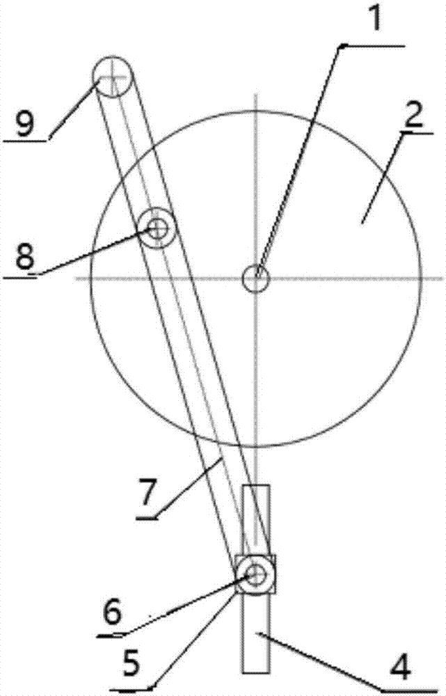
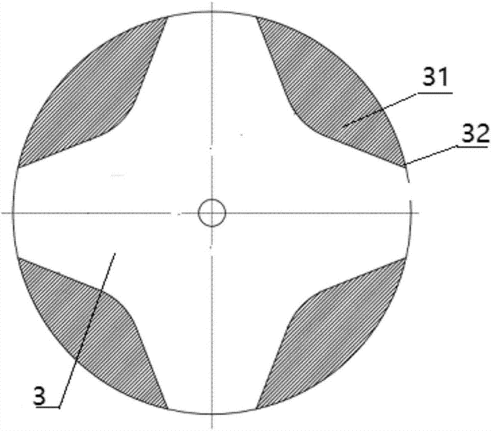
[0022] The present invention is described in detail in conjunction with the accompanying drawings and with the following embodiments: see attached figure 1 , attached figure 2 , attached image 3 , the present invention relates to an intermittent rotary machining workbench, similarly, the present invention can also be used for the assembly line rotary platform required for intermittent production. It includes a central shaft 1 and a disc 2 fixed on the central shaft 1 and rotating together with the central shaft. The disc is connected with the connecting rod 7 through the pin shaft 8, and the other end of the connecting rod is connected with the slip ring 5 through the pin shaft 6. The ring 5 slides freely on the guide rod 4; the extension end of the connecting rod 7 moves along the outline 32 of the groove in the special structure groove 31 on the back of the workbench 3 through the contact 9, so that the workbench can be pushed to realize intermittent movement. Especially...
PUM
 Abstract
Description
Claims
Application Information