
Electronic expansion valve

A technology of electronic expansion valve and valve needle, which is applied in the direction of lift valve, valve device, lighting and heating equipment, etc., can solve problems such as flow increase

Inactive Publication Date: 2017-12-12
ZHEJIANG DUNAN HETIAN METAL CO LTD
View PDF7 Cites 5 Cited by
  • Summary
  • Abstract
  • Description
  • Claims
  • Application Information

AI Technical Summary

Problems solved by technology

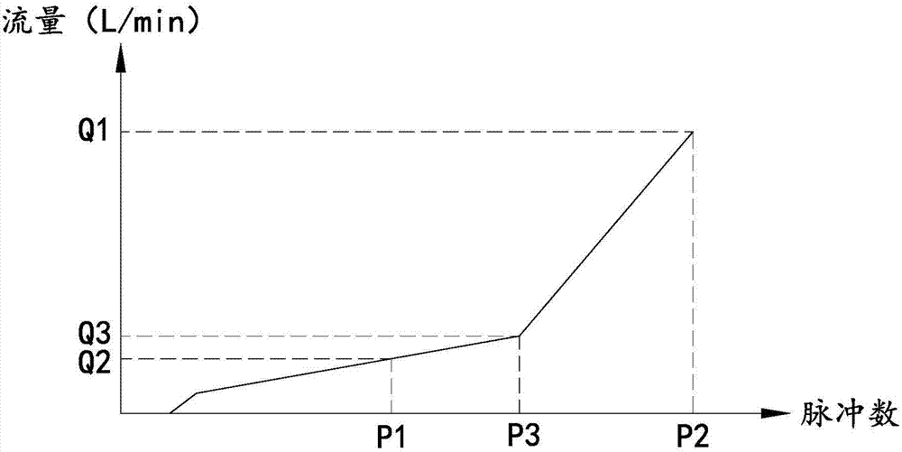
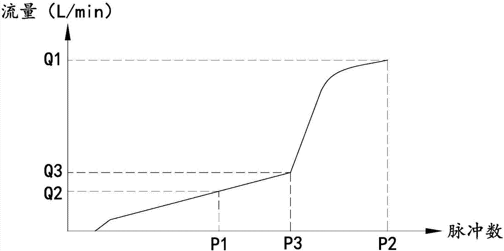
That is, after the P3 pulse, the flow rate needs to increase rapidly, and when it reaches the Q1 flow value, it needs to satisfy: Q1>2Q3, to achieve this kind of flow curve, it is impossible to obtain only the change of the valve needle angle

Method used


Image

  • Electronic expansion valve
  • Electronic expansion valve
  • Electronic expansion valve

Examples


Embodiment 2

[0041] refer to Figure 5 , the electronic expansion valve of this embodiment is substantially the same as that of Embodiment 1, the difference is that the electronic expansion valve of this embodiment also includes a guide sleeve 7, which forms a sliding guide fit with the valve seat core 5, and the guide sleeve 7 is guided when valve seat core 5 moves. Specifically, the guide sleeve 7 of this embodiment is formed by extending upward from the upper part of the valve seat 12, that is, the guide sleeve 7 and the valve seat 12 are integrally formed, which can simplify the processing procedure and reduce the processing cost; the inner wall of the guide sleeve 7 and the outer wall of the valve seat core 5 It forms the sliding-guiding cooperation, which is the basis for the valve needle assembly to guide the valve seat core 5 when it moves, realizes the internal and external guidance of the valve seat core 5 when it moves, further improves the guiding accuracy, and ensures the coax...

Embodiment 3

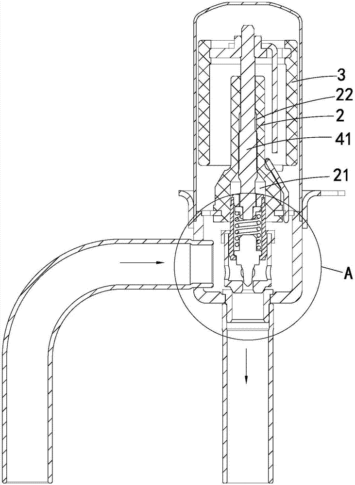
[0045] refer to Figure 6 , the electronic expansion valve of this embodiment is substantially the same as that of the second embodiment, except that the upper part of the guide sleeve 7 protrudes into the cavity 21 of the nut seat 2 and abuts against the inner wall of the cavity 21 . Since the nut seat 2 guides when the valve needle assembly moves, and the valve needle assembly cooperates with the guide sleeve 7 to realize the internal and external guidance of the valve seat core 5 when it moves, the upper part of the guide sleeve 7 is inserted into the cavity 21 of the nut seat 2 and affixed to it. The arrangement on the inner wall of the concave cavity 21 can improve the coaxiality between the nut seat 2 and the guide sleeve 7, further ensure the guiding accuracy of the valve needle and the valve seat core 5 when they move up and down, and realize precise flow control.


PUM


Abstract

The invention discloses an electronic expansion valve, belongs to the field of electromagnetic valves, and solves the problem that a traditional electronic expansion valve cannot obtain the flow curve in application of one special system. The electronic expansion valve comprises a valve body, a valve needle module, and a driving device for driving the valve needle module to move; and the electronic expansion valve controls the driving device according to received pulse signals. The electronic expansion valve further comprises a valve base element mounted on the valve needle module; a small valve port is formed in the valve base element; a large valve port is formed in the valve body; the driving device drives the valve needle module to move to control the openness of the small valve port; and the driving device drives the valve base element to move through the valve needle module so as to control the openness of the large valve port. The electronic expansion valve effectively realizes special flow curve control so as to realize application of the special system.

Description

【Technical field】 [0001] The invention relates to an electronic expansion valve, especially an electronic expansion valve used in air conditioners, refrigerators, heat pumps and the like. 【Background technique】 [0002] The electronic expansion valve is an important part in the refrigeration system, which mainly plays the role of throttling and reducing pressure and regulating flow. The existing electronic expansion valve includes a valve body, a nut, and a valve needle assembly threadedly engaged with the nut. A driving device is used to drive the valve needle assembly to rotate while generating axial movement to adjust the opening of the valve port to achieve flow control. [0003] The flow characteristics of electronic expansion valves are generally described by flow curves. Since most of the existing technologies use conical valve heads that are easy to process, the flow curves of electronic expansion valves are quadratic curves, that is, the left branch of a downward-op...

Claims


Application Information

Patent Timeline
Patent Type & Authority Applications(China)
IPC IPC(8): F16K1/00F25B41/06F16K1/52F16K1/36F16K1/32F25B41/34
CPCF16K1/00F16K1/32F16K1/36F16K1/52F25B41/31Y02B30/70
Inventor 曾庆军陈勇好王定军
Owner ZHEJIANG DUNAN HETIAN METAL CO LTD
Learn More