
Ultra-short bolt wedge load testing clamp and experimental method applying same

A technology of load test and bolt, applied in the direction of applying stable tension/pressure to test the strength of materials, measuring devices, instruments, etc., can solve the problems of insufficient clamping section, inability to carry out tests, space occupied by wedge pads, etc. The effect of convenient installation, shortened test period and simple structure

Inactive Publication Date: 2017-12-12
725TH RES INST OF CHINA SHIPBUILDING INDAL CORP
View PDF8 Cites 4 Cited by
  • Summary
  • Abstract
  • Description
  • Claims
  • Application Information

AI Technical Summary

Problems solved by technology

[0004] The purpose of the present invention is to solve the problem that the same layer of the existing clamp used for ultra-short bolt wedge load test uses wedge pads. Since the wedge pads are generally thin, deformation and failure are prone to occur during repeated use, and the wedge pads need to be replaced periodically. On the one hand Increased test costs, on the other hand also caused waste of materials
In addition, more importantly, because the wedge pad occupies a certain space, some ultra-short and high-strength bolts cannot be tested due to insufficient clamping sections. A fixture and application for ultra-short bolt wedge load tests are provided. its method of experimenting

Method used


Image

  • Ultra-short bolt wedge load testing clamp and experimental method applying same
  • Ultra-short bolt wedge load testing clamp and experimental method applying same
  • Ultra-short bolt wedge load testing clamp and experimental method applying same

Examples


Embodiment Construction

[0025] As shown in the figure, the specific implementation method is as follows:

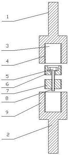
[0026] A clamp for ultra-short bolt wedge load test, comprising a first main clamp 4 and a second main clamp 9, the first main clamp 4 and the second main clamp 9 are cylindrical structures with the same structure, the first main clamp One end of the clamp 4 is connected with the first clamping part 1 for connecting the first main clamp 4 to the clamp on the tensile testing machine, and the end of the first main clamp 4 away from the first clamping part 1 is dug with a second A threaded counterbore 3, one end of the second main clamp 9 is connected with the second clamp 2 for connecting the second main clamp 9 to the upper and lower jaws of the tensile testing machine, the first clamp 1 and The second clamping part 2 is a rectangular parallelepiped clamping rod (or splint), and the end of the second main clamping fixture 9 away from the second clamping part 2 is dug with a second threaded counte...


PUM


Abstract

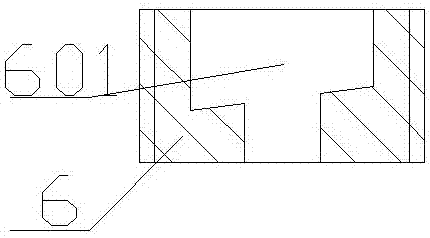
Disclosed are an ultra-short bolt wedge load testing clamp and an experimental method applying same. The ultra-short bolt wedge load testing clamp comprises a first main clamp and a second main clamp, wherein the inside of the first main clamp is threadedly provided with a first connector, and the inside of the second main clamp is threadedly provided with a second connector; the stud of a bolt to be detected sequentially penetrates through the countersink and the through hole of the first connector and is screwed into the threaded hole of the second connector, the screw head of the bolt to be detected is clamped into the countersink of the first connector, the first connector is screwed into the first main clamp and the second connector is screwed into the second main clamp to clamp the bolt to be detected onto an experimental machine. According to the ultra-short bolt wedge load testing clamp, the first connector is provided with the countersink with an inclined bottom surface to form a sunk concave structure and accordingly can meet the requirements of wedge load testing of ultra-short bolts. The ultra-short bolt wedge load testing clamp overcomes the restriction led to by the length of the bolts to testing processes, and achieves wedge load testing on bolts of different specification and performance levels through one set of clamp.

Description

technical field [0001] The invention relates to a wedge load test device, in particular to a fixture for an ultra-short bolt wedge load test and an experiment method using it. Background technique [0002] With the rapid development of China's economy, a large number of infrastructure projects continue to emerge. As one of the main connection forms of various steel structures, bolts have very important applications in various project engineering and mechanical equipment. In recent years, various failure accident cases and published literature have shown that there are various forms of bolt fracture. Although the bolt is small, its quality has a strong impact on engineering quality and equipment safety. The bolt wedge load test is one of the bolt mechanical performance test items. Its purpose is to test the connection performance between the bolt head and the shank, and to prevent the phenomenon of bolt breakage. During the test, a wedge pad is added under the bolt head, m...

Claims


Application Information

Patent Timeline
IPC IPC(8): G01N3/04G01N3/08
CPCG01N3/04G01N3/08G01N2203/0017G01N2203/0067G01N2203/0423
Inventor 董明洪党恒耀李慧
Owner 725TH RES INST OF CHINA SHIPBUILDING INDAL CORP
Learn More