

Camera parameter calibration method based on GPS
A camera parameter and calibration method technology, which is applied in the field of GPS-based camera parameter calibration, can solve problems such as errors and inability to fully meet accuracy requirements, and achieve the effect of improving accuracy and precision and avoiding low precision
- Summary
- Abstract
- Description
- Claims
- Application Information
AI Technical Summary
Problems solved by technology
Method used
Image

Examples
Embodiment Construction
[0025] It is easy to understand that, according to the technical solution of the present invention, those skilled in the art can imagine various implementations of the GPS-based camera parameter calibration method of the present invention without changing the essence of the present invention. Therefore, the following specific embodiments and drawings are only exemplary descriptions of the technical solution of the present invention, and should not be regarded as the entirety of the present invention or as a limitation or limitation on the technical solution of the present invention.
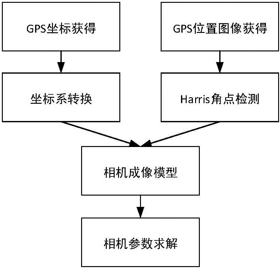
[0026] One, basic thought of the present invention
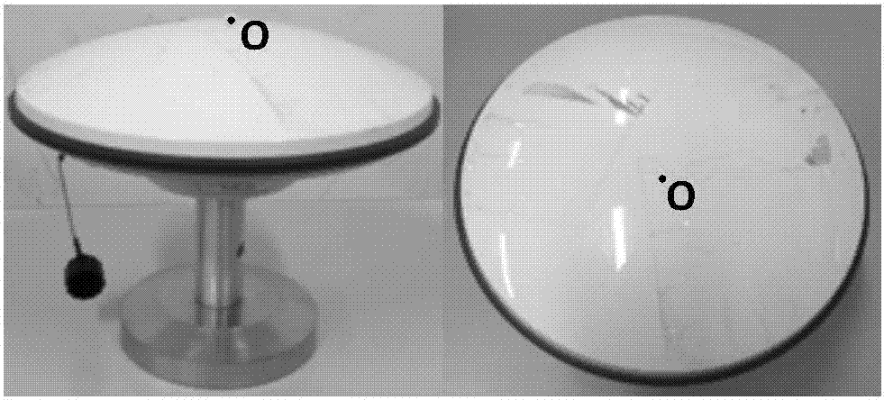
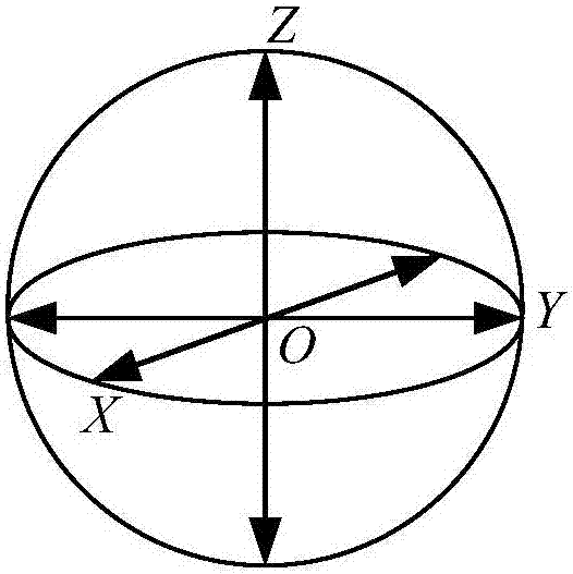
[0027] First, obtain the longitude, latitude and height coordinate information of the centroid of the GPS receiving antenna in the WGS-84 coordinate system through the GPS receiving antenna, and at the same time use the camera to collect images of the GPS receiving antenna at different positions;
[0028] Then, coordinate conversion is performe...
PUM
 Abstract
Description
Claims
Application Information