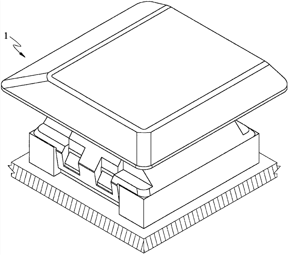
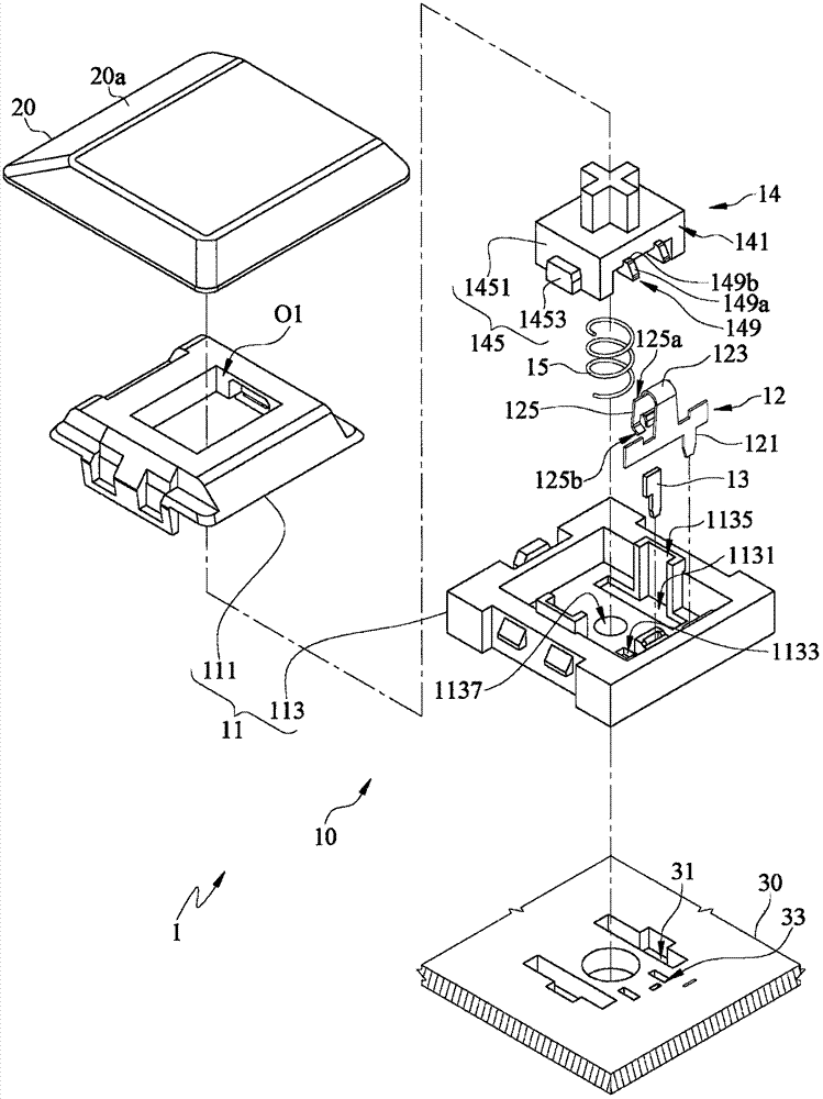
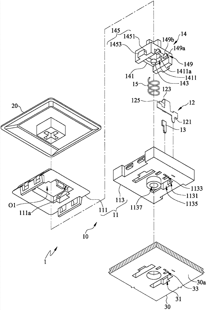
Key assembly and mechanical-type keyboard
A key and component technology, applied in the direction of electrical components, electrical switches, circuits, etc., can solve problems such as the total height and thickness of the keys
Active Publication Date: 2017-12-12
GIGA BYTE TECH CO LTD
3 Cites 0 Cited by
AI-Extracted Technical Summary
Problems solved by technology
[0005] The present invention is to provide a button assembly, thereby sol...
Method used
In order to further make the key thinner, another embodiment of the application also improves the keyboard key, and at least one hole (such as The third relief groove 31) shown in Figure 2A), so that the axis of the key switch can pass through the opening on the base (such as the first relief groove 1131) deep into the opening on the circuit board (such as the third relief groove 1131) Groove 31), further reduce the height of the key switch and the keycap (the reduced height can correspond to the thickness of the circuit board), so that the height of the key can be reduced under the premise that the total stroke of the key remains unchanged.
In order to realize the thinning of the mechanical keyboard keys, without affecting the advantages of the mechanical keyboard such as stable hand feel and long life, the hand feel mainly depends on the pressing pressure and stroke, and the life-span influencing factors mainly lie in the durability of the light touch switch , an embodiment of the present application improves the keyboard keys, the improvement point is: at least one hole is opened on the key base (the lower housing 113 of the base 11 as shown in Figure 2A) (the first abdication as shown in Figure 2A Groove 1131), so that the sum of the height of the key switch (the base 11 and its internal components as shown in Figure 2A) and the keycap (the k...
Abstract
The invention discloses a key assembly and a mechanical-type keyboard. The key assembly comprises a key switch and a key cap. The key switch comprises a pedestal and a press part. The pedestal is provided with an opening, a cavity, and a first abdicating groove. Two opposite ends of the cavity are respectively communicated with the opening and the abdicating groove. The press part is movably located in the cavity, and makes reciprocating motion between a releasing position and a press position. The press part comprises an assembly part and a guide part. The guide part is bulged at one part, far from the opening, of the assembly part, and is corresponding to the first abdicating groove. The key cap is assembled on the assembly part. When the press part is located at the releasing position, the assembly part and the guide part leaves from the first abdicating groove. When the press part moves to the press position from the releasing position, the assembly part gets close to the pedestal, and enables at least a part of the guide part to enter the first abdicating groove.
Application Domain
Electric switches
Technology Topic
Key switchEngineering +1
Image
Examples
- Experimental program(1)
Example Embodiment
[0080] The detailed features and advantages of the present invention are described in detail in the following embodiments. The content is sufficient to enable any person skilled in the art to understand the technical content of the present invention and implement it accordingly, and according to the content disclosed in this specification, claims and drawings, Any person skilled in the art can easily understand the related objectives and advantages of the present invention. The following examples further illustrate the viewpoint of the present invention in detail, but do not limit the scope of the present invention by any viewpoint.
[0081] In order to realize the thinning of the keys of the mechanical keyboard without affecting the advantages of the mechanical keyboard such as stable hand feeling and long life, the hand feeling mainly depends on the pressing pressure and stroke, and the life influence factor mainly lies in the durability of the touch switch. An embodiment improves the keyboard keys, the improvement point is: in the key base (such as Figure 2A The lower shell 113 of the base 11 is shown at least one hole (such as Figure 2A As shown in the first give way slot 1131), the key switch (such as Figure 2A The base 11 and its internal components shown) and key caps (such as Figure 2A The sum of the height of the keycap 20 shown is reduced compared to the traditional height, and the reduced height corresponds to the thickness of the opening on the base 11 (for example, the first relief groove 1131) to ensure that the total stroke of the key remains unchanged ( For example, it is still 4 mm).
[0082] In order to further make the keys thinner, another embodiment of the present application also improves the keyboard keys. On the circuit board corresponding to the key switch (such as Figure 2A At least one hole (such as Figure 2A The shown third relief slot 31), so that the axis of the key switch can pass through the opening on the base (for example, the first relief slot 1131) into the opening on the circuit board (for example, the third relief slot 31) ) To further reduce the height of the key switch and the key cap (the height reduced again can correspond to the thickness of the circuit board), so that the key height can be reduced under the premise that the total stroke of the key remains unchanged.
[0083] In addition, in addition to improving to reduce the height of the key, another embodiment of the present application also provides at least one guide rail or guide groove (for example, Figure 2A The shown guide chute 1135, guide groove 1137, etc.), so as to assist the axis movement of the key switch not to deviate from the center during the pressing process.
[0084] Hereinafter, the application will be described in detail through specific embodiments in conjunction with the accompanying drawings.
[0085] First, see figure 1 , figure 1 It is a three-dimensional view of a key assembly according to an embodiment of the present invention. Such as figure 1 As shown, the present embodiment provides a key assembly 1 which can be applied to the keyboard of electronic products such as notebook computers or desktop computers for inputting specific command signals on the keyboard.
[0086] Next, see Figure 2A~Figure 2B , Figure 2A~Figure 2B These are respectively exploded views of the key assembly according to an embodiment of the present invention in different viewing angles.
[0087] Such as Figure 2A and Figure 2B As shown, the key assembly 1 includes a key switch 10 and a key cap 20. The key cap 20 is assembled on the key switch 10. The key switch 10 is arranged on a circuit board 30. The circuit board 30 can be electrically connected to the system in the aforementioned electronic product through wires (not shown), but the present invention is not limited to this. And it is understandable that more button assemblies 1 can be provided on the circuit board 30.
[0088] Furthermore, the key switch 10 includes a base 11, a conductive elastic sheet 12, a conductive member 13, a pressing member 14 and an elastic member 15.
[0089] The base 11 includes an upper shell 111 and a lower shell 113. The upper shell 111 can be assembled with the lower shell 113 to jointly surround a cavity S1 (such as Figure 4A Shown). The upper shell 111 has an opening O1 connected to the side of the cavity S1 facing the keycap 20. The lower housing 113 is assembled on the circuit board 30.
[0090] In addition, in this embodiment, the lower housing 113 has two first relief grooves 1131, two second relief grooves 1133, two guide sliding grooves 1135, and a guide groove 1137 connected to the cavity S1. . The two first relief grooves 1131, the two second relief grooves 1133 and the guide groove 1137 are all located on the side of the cavity S1 away from the opening O1. Furthermore, the two first relief slots 1131 are opposite to each other, and the two second relief slots 1133 and the guide groove 1137 are both located between the two first relief slots 1131. The two guiding sliding grooves 1135 are respectively connected to the two first relieving grooves 1131 and are respectively located on the two inner side walls of the lower casing 113. The upper casing 111 has a stopping surface 111 a facing the direction of the lower casing 113.
[0091] The conductive elastic sheet 12 is made of a metal material with both conductivity and elastic deformation ability, and includes an assembly section 121, a bending section 123 and a movable section 125. The assembly section 121 is inserted into the lower casing 113 of the base 11 to be electrically connected to the circuit board 30 under the lower casing 113. The movable section 125 has a first end 125a and a second end 125b opposite to each other. The curved section 123 is connected between the first end 125 a of the assembly section 121 and the movable section 125.
[0092] The conductive member 13 is made of a conductive metal material, and is inserted into the lower casing 113 of the base 11 to be electrically connected to the circuit board 30 under the lower casing 113. In addition, a distance is maintained between the conductive element 13 and the assembly section 121 of the conductive elastic sheet 12.
[0093] The pressing member 14 includes an assembling part 141, a guiding pillar 143, two guiding parts 145, and two protrusions 149. The pressing member 14 is movably located in the cavity S1 of the base 11 and can move back and forth between a release position and a pressing position. However, the description of the release position and the pressing position will be detailed later.
[0094] The keycap 20 is assembled on the side of the assembling portion 141 of the pressing member 14 that faces away from the lower housing 113 of the base 11 and covers the opening O1 of the base 11. In this embodiment, the side of the keycap 20 facing the assembling portion 141 has a cross-shaped groove, and the side of the assembling portion 141 facing the keycap 20 has a cross-shaped protrusion matching the cross-shaped groove for The key cap 20 is assembled to the pressing member 14. In addition, the assembling part 141 has a groove 1411 located on the side of the assembling part 141 facing the lower casing 113 of the base 11.
[0095] The guiding pillar 143 protrudes from a groove bottom surface 1411 a of the groove 1411 from the groove 1411, and the guiding pillar 143 corresponds to the guiding groove 1137 of the lower casing 113. The elastic member 15 is a compression spring installed (eg sleeved) on the guide post 143 and movably located between the bottom surface 1411 a of the groove 1411 of the assembling portion 141 and the lower shell 113 of the base 11.
[0096] Each guiding portion 145 includes an extension section 1451 and a guiding protrusion 1453. The two extension sections 1451 protrude from the side of the assembling part 141 facing the lower housing 113 of the base 11 (or protruding from the side of the assembling part 141 away from the opening O1 of the upper housing 111 ). The two guiding protrusions 1453 are respectively disposed on a side of the two extension sections 1451 away from the assembling portion 141, and are respectively slidably located in the two guiding sliding grooves 1135. In this embodiment, the extension section 1451 and the guiding protrusion 1453 correspond to the first relief groove 1131 of the lower housing 113. In addition, in this embodiment, the circuit board 30 has two third relief slots 31 and two fourth relief slots 33. The two third relief slots 31 respectively correspond to the two first relief slots 1131 of the base 11. The two fourth relief slots 33 respectively correspond to the two second relief slots 1133 of the base 11. However, it should be stated that the present invention is not limited to the third recess 31 and the fourth recess 33 of the circuit board 30.
[0097] The two bumps 149 protrude from the side of the assembly portion 141 facing the movable section 125 of the conductive elastic sheet 12. Each bump 149 has a guiding inclined surface 149a and a top abutting surface 149b. The guiding inclined surface 149a and the abutting surface 149b are both located on the side of the protrusion 149 facing the upper casing 111 of the base 11. The guiding inclined surface 149a is closer to the conductive elastic sheet 12 than the top surface 149b, and corresponds to the second end 125b of the movable section 125. The abutting surface 149b corresponds to the stopping surface 111a of the upper casing 111.
[0098] Next, it should be stated that the present invention does not use the first relief slot 1131, the second relief slot 1133 and the guide chute 1135 of the base 11, and the third relief slot 31 and the fourth relief slot of the circuit board 30. The number of 33 is limited. For example, in other embodiments, the number of the first relief slot 1131, the second relief slot 1133, the third relief slot 31, the fourth relief slot 33, and the guide chute 1135 may all be one. In this case, the number of guide portions 145 corresponding to the first relief groove 1131 and the third relief groove 31, and the number of protrusions 149 corresponding to the second relief groove 1133 and the fourth relief groove 33 may also be used. All are one, and they are not used to limit the present invention. In addition, the present invention is not limited to the specifications of the third relief slot 31 and the fourth relief slot 33. For example, in other embodiments, the third relief slot 31 and the fourth relief slot 33 may not penetrate the circuit board 30.
[0099] In addition, the present invention is not limited to the positions of the aforementioned guide post 143 and the guide groove 1135. For example, in other embodiments, the guiding post 143 may also be disposed on the lower housing 113 and extend toward the pressing member 14, and the guiding groove 1135 is located on the side of the pressing member 14 facing the lower housing 113.
[0100] Next, the operation mode of the key assembly 1 will be described. See Figure 3~4C , image 3 Is a bottom view of the button assembly according to an embodiment of the present invention, Figure 4A for image 3 The pressing member of the button assembly is located in the release position and is a side sectional view drawn along the 4A-4A section line, Figure 4B for Figure 4A Side sectional view of the pressing member of the button assembly in the pressing position, and Figure 4C for image 3 The pressing member of the button assembly is located at the pressing position and is a side sectional view drawn along the 4C-4C section line. Among them, it should be noted that for the purpose of conciseness and clarity of the drawings, image 3 The circuit board 30 is shown as a dotted line, and the key assembly 1 is shown as a solid line.
[0101] First, like Figure 4A As shown, when the pressing member 14 is in the release position, the assembling portion 141 is pushed by the elastic member 15 and the guiding portion 145 is relatively far away from the first recess 1131 of the base 11. In addition, the protrusion 149 of the pressing member 14 pushes against the movable section 125 of the squeezing conductive elastic sheet 12 so that the second end 125 b of the movable section 125 is relatively close to the assembly section 121 and maintains a distance from the conductive member 13. In this case, the conductive elastic sheet 12 and the conductive member 13 are not electrically connected. In addition, since the movable section 125 is compressed, the curved section 123 will accumulate elastic potential energy. In addition, the abutting surface 149b of the protrusion 149 of the pressing member 14 will abut against the stopping surface 111a of the upper casing 111 to prevent the pressing member 14 from leaving the cavity S1 from the opening O1.
[0102] Next, please join Figure 4A Continued reference Figure 4B versus Figure 4C. The user can force the keycap 20 in the direction of arrow A to push the pressing member 14 from the release position to the pressing position. During this process, the assembling part 141 will be relatively close to the lower shell 113 of the base 11, and drive the guiding part 145 (including the guiding protrusion 1453 and at least part of the extension section 1451) into the first relief groove of the lower shell 113 1131, and at least part of the guide post 143 enters the guide groove 1137 of the lower housing 113. Among them, by Figure 4A to Figure 4B It can be seen that since the guiding protrusion 1453 can slide in the guiding chute 1135, the pressing member 14 can be restricted from sliding in a predetermined direction relative to the base 11 and help to reduce the shaking generated during pressing. In addition, the assembling part 141 compresses the elastic element 15 so that the elastic element 15 accumulates elastic potential energy.
[0103] When the pressing member 14 is at the pressing position, the guiding portion 145 (including the guiding protrusion 1453 and at least part of the extension section 1451) will sequentially pass through the first recess 1131 of the lower housing 113 and the circuit board 30 The third relief groove 31 and the protrusion 149 respectively penetrate the two second relief grooves 1133 of the lower housing 113 and the fourth relief groove 33 of the circuit board 30. In addition, the bump 149 is relatively close to the lower shell 113 and no longer presses against the movable section 125 of the conductive elastic sheet 12, so that the elastic potential energy accumulated by the curved section 123 can be released, so as to elastically guide the second end 125b of the movable section 125 The electrical member 13 is in contact with the conductive member 13 and is electrically conducted. Thus, the signal scheduled to be sent by the key assembly 1 can be triggered.
[0104] In an actual implementation, when the pressing member 14 is in the release position (such as Figure 4A (Shown), because the base 11 is provided with a first recess 1131, the guiding portion 145 of the pressing member 14 can penetrate the base 11, and the circuit board 30 is also provided with a third recess 31 so that the pressing member 14 penetrates the circuit The board 30 is such that, first, the distance h1 from the upper surface of the upper casing 111 to the upper surface of the circuit board 30 is reduced from 10.7 mm of a traditional mechanical button to 5.0 mm in an embodiment of the application. Secondly, the distance h2 from the upper surface of the assembling part 141 to the upper surface of the upper casing 111 is reduced from 4.1 mm of a traditional mechanical button to 2.2 mm of an embodiment of the application. In addition, the distance h3 from the upper surface of the keycap 20 to the upper surface of the assembling portion 141 is reduced from 6.7 mm of the traditional mechanical key to 1.3 mm of an embodiment of the application. Obviously, the total thickness from the upper surface of the keycap 20 to the upper surface of the circuit board 30 is reduced from the traditional 21.5 mm to 8.5 mm, but the total stroke of the key can still be kept unchanged, for example, 4 mm.
[0105] That is, in the key assembly 1 disclosed in the present invention, when the pressing member 14 is pressed to the pressing position, since the guide portion 145 can penetrate the first recess 1131 of the base 11, the stroke of the touch can be maintained Under the premise of 4 mm (a pressing stroke recognized as having a better touch feel), the thickness of the base 11 and the key cap 20 is reduced to reduce the overall thickness of the key assembly 1 when it is not pressed to 10 mm, that is, far It is much lower than the specifications of traditional mechanical keys with a total thickness of 25 mm, which is conducive to the production trend of thinner electronic products.
[0106] Then, it is understandable that when the user cancels the force applied to the keycap 20, the elastic member 15 can release the aforementioned accumulated elastic potential energy and push the pressing member 14 from the pressing position (such as Figure 4B versus Figure 4C ) Spring back to release position (e.g. Figure 4A ). During this process, the guiding inclined surface 149a on the bump 149 first abuts the second end 125b of the movable section 125 of the conductive spring 12, so as to squeeze the second end 125b and approach the assembly section 121 again, so that the second end 125b returns to the state separated from the conductive member 13.
[0107] Also, see Figure 5 , Figure 5 It is a three-dimensional view of a mechanical keyboard according to an embodiment of the invention. As shown in the figure, a mechanical keyboard 9 is provided, which includes a keyboard housing 91, a plurality of key assemblies 1 as described above, and a circuit board 30 as described above. The key assembly 1 and the circuit board 30 are both arranged in the keyboard housing 91. The key components 1 are electrically connected to the circuit board 30 so as to trigger their predetermined signals.
[0108] Although the present invention is disclosed in the foregoing embodiments, it is not intended to limit the present invention. All changes and modifications made without departing from the spirit and scope of the present invention belong to the scope of patent protection of the present invention. For the protection scope defined by the present invention, please refer to the appended claims.
PUM


Description & Claims & Application Information
We can also present the details of the Description, Claims and Application information to help users get a comprehensive understanding of the technical details of the patent, such as background art, summary of invention, brief description of drawings, description of embodiments, and other original content. On the other hand, users can also determine the specific scope of protection of the technology through the list of claims; as well as understand the changes in the life cycle of the technology with the presentation of the patent timeline. Login to view more.