Storage and mixing device for bone cement with a pressure pump
A mixing device and bone cement technology, applied in mixers with rotating stirring devices, liquid and solid mixing, mixing machines, etc., can solve problems such as complex structures, reduce the risk of failure, and achieve safe operability Effect
- Summary
- Abstract
- Description
- Claims
- Application Information
AI Technical Summary
Problems solved by technology
Method used
Image

Examples
Embodiment Construction
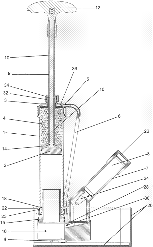
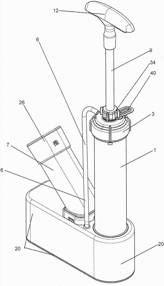
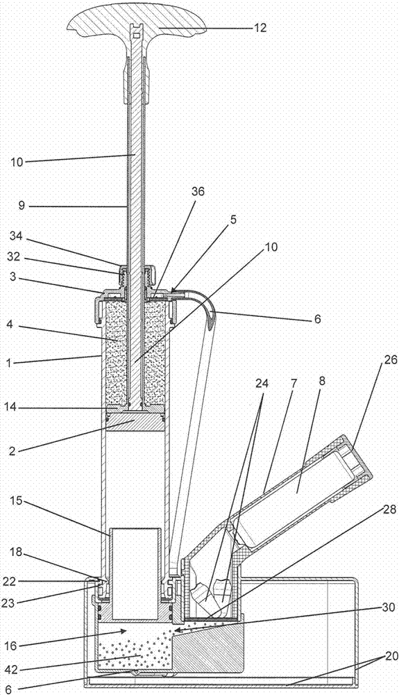
[0187] Figures 1 to 6 An exemplary embodiment of a first storage and mixing device of the present invention is shown. here, figure 1 A schematic cross-sectional view of a first exemplary storage and mixing device of the present invention is shown in an initial state. The storage and mixing device comprises a cartridge 1 with a cylindrical interior in which a plunger 2 is arranged to be linearly movable in the axial direction. On the front side of the cartridge 1 ( figure 1 and 3 to 5, at the top), the interior or cartridge 1 is closed by a cartridge head 3 similar to a cap or cap. The cartridge head 3 is sealed against the cartridge 1 by means of a circumferential seal. In the interior of the cartridge 1 , the bone cement powder 4 as the first matrix component 4 of PMMA bone cement is located between the plunger 2 and the cartridge head 3 .
[0188] The plunger 2 is in gas-tight contact with the inner wall of the interior of the cartridge 1 by means of a circumferential...
PUM
 Abstract
Description
Claims
Application Information
 - R&D
- Intellectual Property
- Life Sciences
- Materials
- Tech Scout
- Unparalleled Data Quality
- Higher Quality Content
- 60% Fewer Hallucinations
Browse by: Latest US Patents, China's latest patents, Technical Efficacy Thesaurus, Application Domain, Technology Topic, Popular Technical Reports.
© 2025 PatSnap. All rights reserved.Legal|Privacy policy|Modern Slavery Act Transparency Statement|Sitemap|About US| Contact US: help@patsnap.com