Wind wheel roller press

A rolling machine and wind wheel technology, applied in the direction of metal processing equipment, etc., can solve the problems of not reaching the design size, high product scrap rate, low assembly stability, etc., to improve assembly quality, low wind wheel defect rate, The effect of reasonable structural design

Pending Publication Date: 2017-12-15
JIANGXI HENGCHENG IND
View PDF0 Cites 0 Cited by
  • Summary
  • Abstract
  • Description
  • Claims
  • Application Information

AI Technical Summary

Problems solved by technology

[0002] At present, the process adopted by the traditional cross-flow wind wheel and vortex wind wheel on the market is completed by the following steps: 1. Slitting the aluminum strip of the blade; 2. Stamping or rolling the slit aluminum strip. 3. Slitting the spacer material; 4. Stamping the cut spacer material to make a spacer; 5. Manually put the leaves one by one on the spacer; 6. Then pass through The assembled wind wheel is rolled and formed by special rolling equipment; 7. Use the balance machine to adjust the balance of the product; 8. Oxidize the finished product, but the assembly stability of the existing rolling equipment after rolling Low, the design size cannot be reached after assembly and molding, and the product scrap rate is high, and the versatility is poor. Different products often need different equipment for rolling. In view of this, it is necessary to design a wind wheel rolling machine to solve the problem. above question

Method used


Image

  • Wind wheel roller press
  • Wind wheel roller press
  • Wind wheel roller press

Examples


Embodiment 1

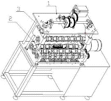
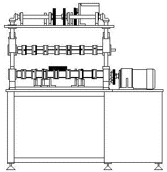
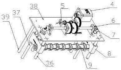
[0036] Example 1, see figure 1 —— Figure 6 , a wind wheel rolling machine, comprising a frame, an upper rolling wheel mechanism 1 and a lower rolling wheel mechanism 2, the lower rolling wheel mechanism 2 is arranged on the frame table, and the lower rolling wheel mechanism 2 is provided with The upper rolling wheel mechanism 1 and the lower rolling wheel mechanism 2 include a lower rolling wheel device 11, a gear seat 12, an axial limit device 13 and a driving device for driving each lower rolling wheel device 11 to rotate, and the two sides of the frame table are A gear seat 12 is provided, and the gear seat 12 includes a bottom plate and two side plates, and an axial limit device 13 is provided for sliding on the bottom plate, and at least two sets of lower rolling wheel devices 11 are installed between the two side plates; the upper rolling wheel mechanism 1 includes machine plate 38, screw seat 8, upper rolling wheel device 9, short guide post 36, long guide post 37 and...


PUM


Abstract

The invention discloses a wind wheel roller press. The wind wheel roller press comprises a machine frame, an upper rolling wheel mechanism and a lower rolling wheel mechanism. The lower rolling wheel mechanism is arranged on a table board of the machine frame. The upper rolling wheel mechanism is arranged above the lower rolling wheel mechanism. The lower rolling wheel mechanism comprises lower rolling wheel devices, gear stands, an axial limiting device and a driving device used for driving all the lower rolling wheel devices to rotate. The gear stands are arranged at the two sides of the table board of the machine frame and comprise a base plate and two side plates. The base plate is provided with the axial limiting device in a sliding mode. At least two sets of the lower rolling wheel devices are installed between the two side plates. The upper rolling wheel mechanism comprises a machine board, screw rod bases, upper rolling wheel devices, short guide pillars, long guide pillars and a lifting mechanism used for driving the upper rolling wheel devices to be vertically lifted up and down on the short guide pillars and the long guide pillars along with the screw rod bases. The screw rod bases are installed at the two sides below the machine board through the short guide pillars and the long guide pillars in a sliding mode correspondingly. The upper rolling wheel devices are installed between the two screw rod bases. By means of the wind wheel roller press, one-time rolling can be achieved in place, and the wind wheel roller press can be used for rolling different models of products.

Description

technical field [0001] The invention relates to a wind wheel rolling machine. Background technique [0002] At present, the process adopted by the traditional cross-flow wind wheel and vortex wind wheel on the market is completed by the following steps: 1. Slitting the aluminum strip of the blade; 2. Stamping or rolling the slit aluminum strip. 3. Slitting the spacer material; 4. Stamping the cut spacer material to make a spacer; 5. Manually put the leaves one by one on the spacer; 6. Then pass through The assembled wind wheel is rolled and formed by special rolling equipment; 7. Use the balance machine to adjust the balance of the product; 8. Oxidize the finished product, but the assembly stability of the existing rolling equipment after rolling Low, the design size cannot be reached after assembly and molding, and the product scrap rate is high, and the versatility is poor. Different products often need different equipment for rolling. In view of this, it is necessary to ...

Claims


Application Information

Patent Timeline
IPC IPC(8): B21D53/26
CPCB21D53/267
Inventor 林中云
Owner JIANGXI HENGCHENG IND
Why Eureka
Try Eureka