Water-cooling stirring head used for friction stir welding and water cooling circulation method
A technology of friction stirring and stirring head, which is applied in welding equipment, non-electric welding equipment, metal processing equipment, etc., can solve the problems of complex structure of stirring head, high manufacturing cost, unsatisfactory cooling effect of stirring head, etc., and achieve novel cooling cycle mode , Low manufacturing cost, and the effect of improving welding quality and stability
- Summary
- Abstract
- Description
- Claims
- Application Information
AI Technical Summary
Problems solved by technology
Method used
Image
Examples
Embodiment 1
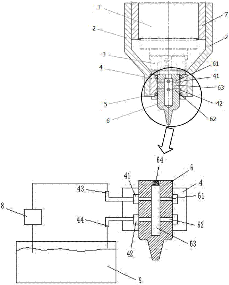
[0026] Such as figure 1The shown water-cooled stirring head for friction stir welding mainly includes a main shaft 1, a fixed frame 2, a handle 3, a sheath 4, a sealing ring 5, and a stirring head 6, and the handle 3 is installed on the main shaft 1, the stirring head 6 is mounted on the lower end of the handle 3, the handle 3 and the stirring head 6 rotate with the main shaft 1, the sheath 4 surrounds the outside of the upper half of the stirring head 6, the main shaft 1 The outer surface is covered with a welding equipment shell 7, and the fixed frame 2 is composed of two symmetrical bent plates. Installed on the left and right sides of the outer surface of the sheath 4, the fixed frame 2, the sheath 4, and the welding equipment shell 7 do not rotate with the main shaft 1, and the sheath 4 is provided with a water inlet 43 and a water outlet 44. The water inlet 43 and the water outlet 44 are located in the middle of the front of the sheath 4 one above the other, and are pro...
Embodiment 2
[0035] Embodiment 2: as figure 1 The shown water-cooled stirring head for friction stir welding mainly includes a main shaft 1, a fixed frame 2, a handle 3, a sheath 4, a sealing ring 5, and a stirring head 6, and the handle 3 is installed on the main shaft 1, the stirring head 6 is mounted on the lower end of the handle 3, the handle 3 and the stirring head 6 rotate with the main shaft 1, the sheath 4 surrounds the outside of the upper half of the stirring head 6, the main shaft 1 The outer surface is covered with a welding equipment shell 7, and the fixed frame 2 is composed of two symmetrical bent plates. Installed on the left and right sides of the outer surface of the sheath 4, the fixed frame 2, the sheath 4, and the welding equipment shell 7 do not rotate with the main shaft 1, and the sheath 4 is provided with a water inlet 43 and a water outlet 44. The water inlet 43 and the water outlet 44 are located in the middle of the front of the sheath 4 one above the other, a...
Embodiment 3
[0045] Such as figure 1 The shown water-cooled stirring head for friction stir welding mainly includes a main shaft 1, a fixed frame 2, a handle 3, a sheath 4, a sealing ring 5, and a stirring head 6, and the handle 3 is installed on the main shaft 1, the stirring head 6 is mounted on the lower end of the handle 3, the handle 3 and the stirring head 6 rotate with the main shaft 1, the sheath 4 surrounds the outside of the upper half of the stirring head 6, the main shaft 1 The outer surface is covered with a welding equipment shell 7, and the fixed frame 2 is composed of two symmetrical bent plates. Installed on the left and right sides of the outer surface of the sheath 4, the fixed frame 2, the sheath 4, and the welding equipment shell 7 do not rotate with the main shaft 1, and the sheath 4 is provided with a water inlet 43 and a water outlet 44. The water inlet 43 and the water outlet 44 are located in the middle of the front of the sheath 4 one above the other, and are pr...
PUM
 Abstract
Description
Claims
Application Information
 - R&D
- Intellectual Property
- Life Sciences
- Materials
- Tech Scout
- Unparalleled Data Quality
- Higher Quality Content
- 60% Fewer Hallucinations
Browse by: Latest US Patents, China's latest patents, Technical Efficacy Thesaurus, Application Domain, Technology Topic, Popular Technical Reports.
© 2025 PatSnap. All rights reserved.Legal|Privacy policy|Modern Slavery Act Transparency Statement|Sitemap|About US| Contact US: help@patsnap.com

