Automatic ramming equipment for slope
An automatic and sloped technology, applied in soil protection, construction, infrastructure engineering, etc., can solve the problems of high cost and troublesome use of rammers, and achieve the effect of convenient and firm adsorption of iron blocks and a high degree of automation
- Summary
- Abstract
- Description
- Claims
- Application Information
AI Technical Summary
Problems solved by technology
Method used
Image

Examples
Embodiment Construction
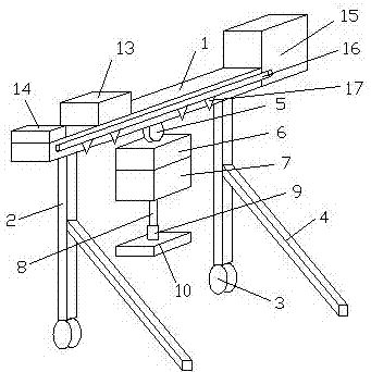
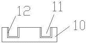
[0022] This application involves the following technical features: horizontal plate 1; column 2; roller 3; support rod 4; drive wheel 5; drive motor 6; hydraulic device 7; hydraulic telescopic rod 8; ; Electromagnet 12; Power box 13; Controller 14; Water storage tank 15; Spray pipe 16;
[0023] figure 1 , 2 The automatic tamping equipment for the slope shown includes a horizontal plate. Two height-adjustable columns are arranged symmetrically under the horizontal plate. Rollers are connected to the bottom of each column, and two supporting rods are movably connected to each column. There is a driving motor connected to the driving wheel, the driving wheel is slidingly connected to the horizontal plate, the lower end of the driving motor is connected to the hydraulic device, the lower end of the hydraulic device is connected to the hydraulic telescopic rod, and the lower end of the hydraulic telescopic rod is detachably connected to the pressure block through the bushing. The...
PUM
 Abstract
Description
Claims
Application Information
 - Generate Ideas
- Intellectual Property
- Life Sciences
- Materials
- Tech Scout
- Unparalleled Data Quality
- Higher Quality Content
- 60% Fewer Hallucinations
Browse by: Latest US Patents, China's latest patents, Technical Efficacy Thesaurus, Application Domain, Technology Topic, Popular Technical Reports.
© 2025 PatSnap. All rights reserved.Legal|Privacy policy|Modern Slavery Act Transparency Statement|Sitemap|About US| Contact US: help@patsnap.com