Middle cooking fume sucking and removing hot pot boiler

A boiler and oil fume technology, which is applied in the field of fire boilers, can solve the problems of low position of oil suction fume, poor effect of oil fume extraction device, large turbulent flow, etc., and achieve the effect of reducing oil fume emission, compact structure and small turbulent flow

Inactive Publication Date: 2017-12-15
陈劲游
View PDF4 Cites 1 Cited by
  • Summary
  • Abstract
  • Description
  • Claims
  • Application Information

AI Technical Summary

Problems solved by technology

[0002] Hot pot is people's favorite way of eating, but it will produce a lot of steam and oily smoke. If you are outdoors, people will be troubled by oily smoke. The oil fume is sucked around the mouth of the hot pot, but the turbulent flow is large and the position of the oil suction mouth is low, so the effect of this oil fume extraction device is not very good

Method used


Image

  • Middle cooking fume sucking and removing hot pot boiler
  • Middle cooking fume sucking and removing hot pot boiler
  • Middle cooking fume sucking and removing hot pot boiler

Examples


Embodiment 1

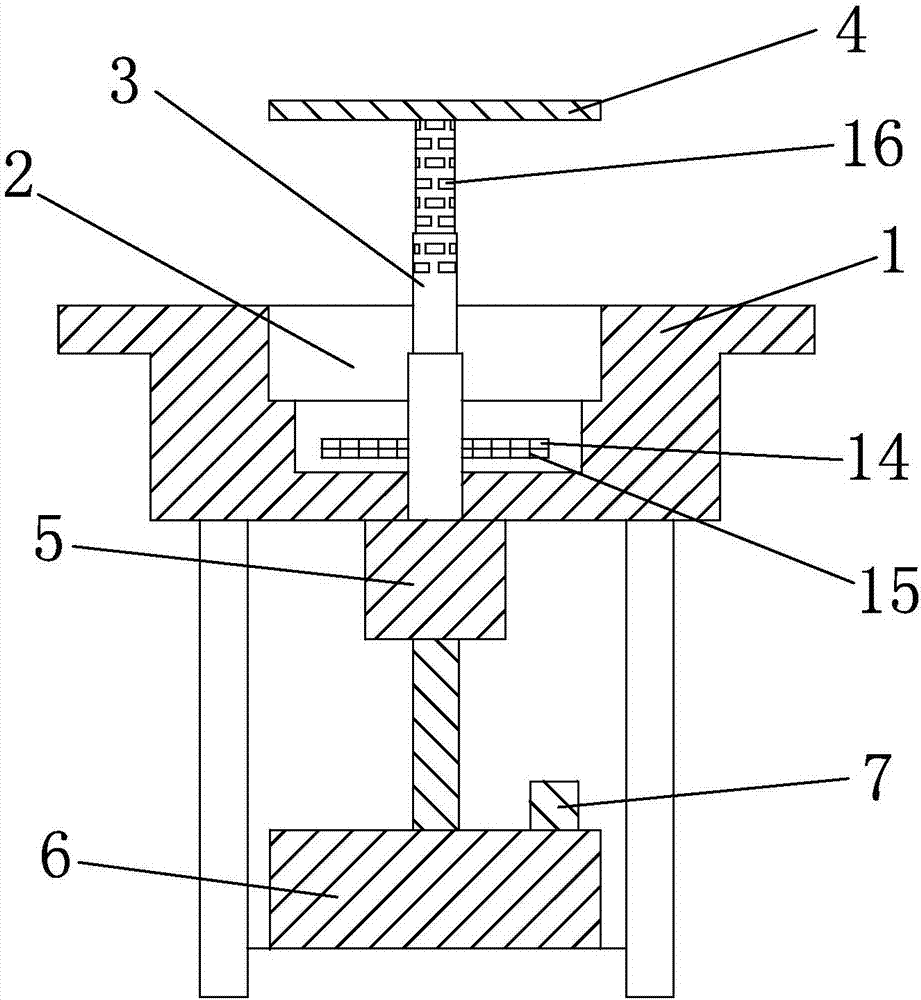
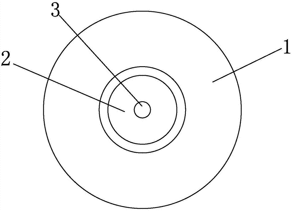
[0029] Such as figure 1 , figure 2 As shown in the figure, a fire boiler with intermediate suction and removal of oil fume is characterized in that it includes a furnace body 1, and a concave cavity 2 is provided on the furnace body 1, and a heating device is provided in the concave cavity 2. The heating device is provided with a chafing dish body 12, and the middle part of the concave cavity 2 is provided with a smoke conduit 3, and the top of the smoke conduit 3 is connected with a smoke collection hood 4, and the smoke conduit 3 is connected from the chafing dish body 12 to the smoke collection hood. 4 is provided with a smoking hole 16, the other end of the smoke duct 3 is connected to the exhaust fan 5, and the output end of the exhaust fan 5 is connected to the oil fume purification box 6, and the oil fume purification box 6 is connected to the exhaust output pipe 7, A chafing dish body 12 is arranged in the concave cavity 2 , and an oil fume purification conduit is ar...

Embodiment 2

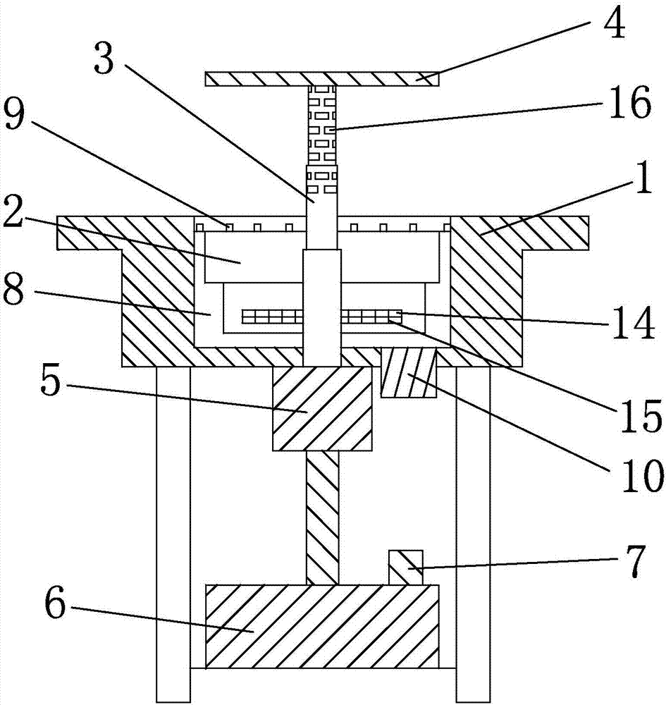
[0033] Such as image 3 and Figure 4 As shown, on the basis of Embodiment 1, an air pressurized chamber 8 is provided between the furnace body 1 and the concave cavity 2, and a plurality of air pressurized chambers 8 are provided on the mouth of the concave cavity 2 to communicate with the air pressurized chamber 8. Compressed air is sprayed vertically upwards to form the air nozzle 9 of the wind screen. The air pressurized chamber 8 is connected with an air compressor 10, which compresses the air and draws it into the air pressurized chamber 8. The compressed air passes through the air nozzle 9 Spray vertically outward at the mouth of the cavity 2, so that the mouth of the cavity 2 forms a wind screen, which can better concentrate the oil fume, prevent the oil fume from spreading outward, and improve the effect of oil fume suction and removal.

Embodiment 3

[0035] Such as Figure 5 As shown, on the basis of Embodiment 2, a return air pipe 11 is connected between the air inlet of the air compressor 10 and the exhaust output pipe 7, so that the air after purifying oil fume enters the air compressor 10, and the compressed air Enter the air pressurization chamber 8 and spray it vertically upward from the air nozzle 9 to form a wind screen, so that most of the purified air re-enters the oil fume purification system for multiple purifications, further reducing the emission of oil fume.

[0036] In Embodiments 1, 2, and 3, the inner wall of the cavity 2 is provided with a vent 14 for replenishing air to the cavity 2 and realizing heat dissipation, and the vent 14 is provided with a tuyere grid 15 to realize the ventilation in the cavity 2. Air replenishment and heat dissipation during the cooking process, the vent 14 is provided with a vent grid 15 to prevent foreign objects from entering the cavity 2 through the vent 14 .

[0037] A s...


PUM


Abstract

The invention discloses a middle cooking fume sucking and removing hot pot boiler. The middle cooking fume sucking and removing hot pot boiler comprises a boiler body provided with a concave cavity. A heating device is arranged in the concave cavity and provided with a hot pot boiler body. A smoke sucking guide pipe is arranged at the middle portion of the concave cavity. A smoke collecting hood is arranged at the top end of the smoke sucking guide pipe. Smoke sucking holes are formed in the part, between the hot pot boiler body and the smoke collecting hood, on the smoke sucking guide pipe, and the other end of the smoke sucking guide pipe is connected with an exhaust fan. The output end of the exhaust fan is connected with a cooking fume purification box connected with an exhaust air output pipe. A main hot pot boiler body is arranged on the heating device, meanwhile, the smoke collecting hood capable of being extended or folded is arranged above the concave cavity, and when the smoke collecting hood is extended to the position above the concave cavity, cooking fume generated in the cooking process can be sucked and removed; and when the smoke collecting hood is folded into the concave cavity, an integral whole is formed. Conversion is convenient, the cooking fume sucking effect is good, and meanwhile when the hot pot boiler is embedded in a dining table, the integral whole can be formed by the folded smoke collecting hood and the dining table top.

Description

[technical field] [0001] The invention relates to a fire boiler for sucking and removing oil fumes in the middle. [Background technique] [0002] Hot pot is people's favorite way of eating, but it will produce a lot of steam and oily smoke. If you are outdoors, people will be troubled by oily smoke. The oil fume is sucked around the hot pot mouth, but the turbulent flow is large, and the position of the oil suction mouth is low, so that the effect of this oil fume extraction device is not very good. [Content of the invention] [0003] The present invention overcomes the deficiencies of the above-mentioned technologies, and provides a fire boiler that absorbs and removes oil fumes in the middle. A cooking heating device is arranged in the concave cavity of the furnace body, a fire boiler is installed on the heating device, and an extendable or retractable boiler is installed above the concave cavity. The folded fume collecting hood, when the fume collecting hood is stretch...

Claims


Application Information

Patent Timeline
Patent Type & Authority Applications(China)
IPC IPC(8): F24C15/20A47B31/02
CPCA47B31/02F24C15/2042
Inventor 谢逸波陈劲游
Owner 陈劲游
Why Eureka
Try Eureka