Method and instrument for real-time terrain measurement of vacuum combined dynamic cement-sand model

A sediment model and terrain measurement technology, applied in the field of measuring instruments, can solve problems such as the existence of suspended sand, turbid water in sediment physical models, and failure of measurement methods, so as to improve measurement accuracy, improve reflection effects, and improve measurement accuracy Effect

Active Publication Date: 2019-06-28
NANJING HYDRAULIC RES INST
View PDF10 Cites 0 Cited by
  • Summary
  • Abstract
  • Description
  • Claims
  • Application Information

AI Technical Summary

Problems solved by technology

However, due to the influence of different media, the ultrasonic measuring instrument must be carried out underwater, limited by the shallow water depth of the estuary and coast model, often only a few centimeters, and the blind area of ​​the instrument is generally 3-5cm (maximum 10cm), and the use is relatively large. limitations
In addition, the sediment physical model water is relatively turbid and there is suspended sediment, and the laser measurement method is also difficult to apply
[0005] Method 3 (dynamic water measurement method), in addition to the defects of the ultrasonic measurement method in method 2, the current ultrasonic measuring instrument has a large probe size, which has a significant impact on the surrounding flow field and terrain under the hydrodynamic test conditions, especially when the water depth is small , which will lead to the failure of the measurement method due to the measurement blind zone

Method used


Image

  • Method and instrument for real-time terrain measurement of vacuum combined dynamic cement-sand model
  • Method and instrument for real-time terrain measurement of vacuum combined dynamic cement-sand model

Examples


Embodiment 1

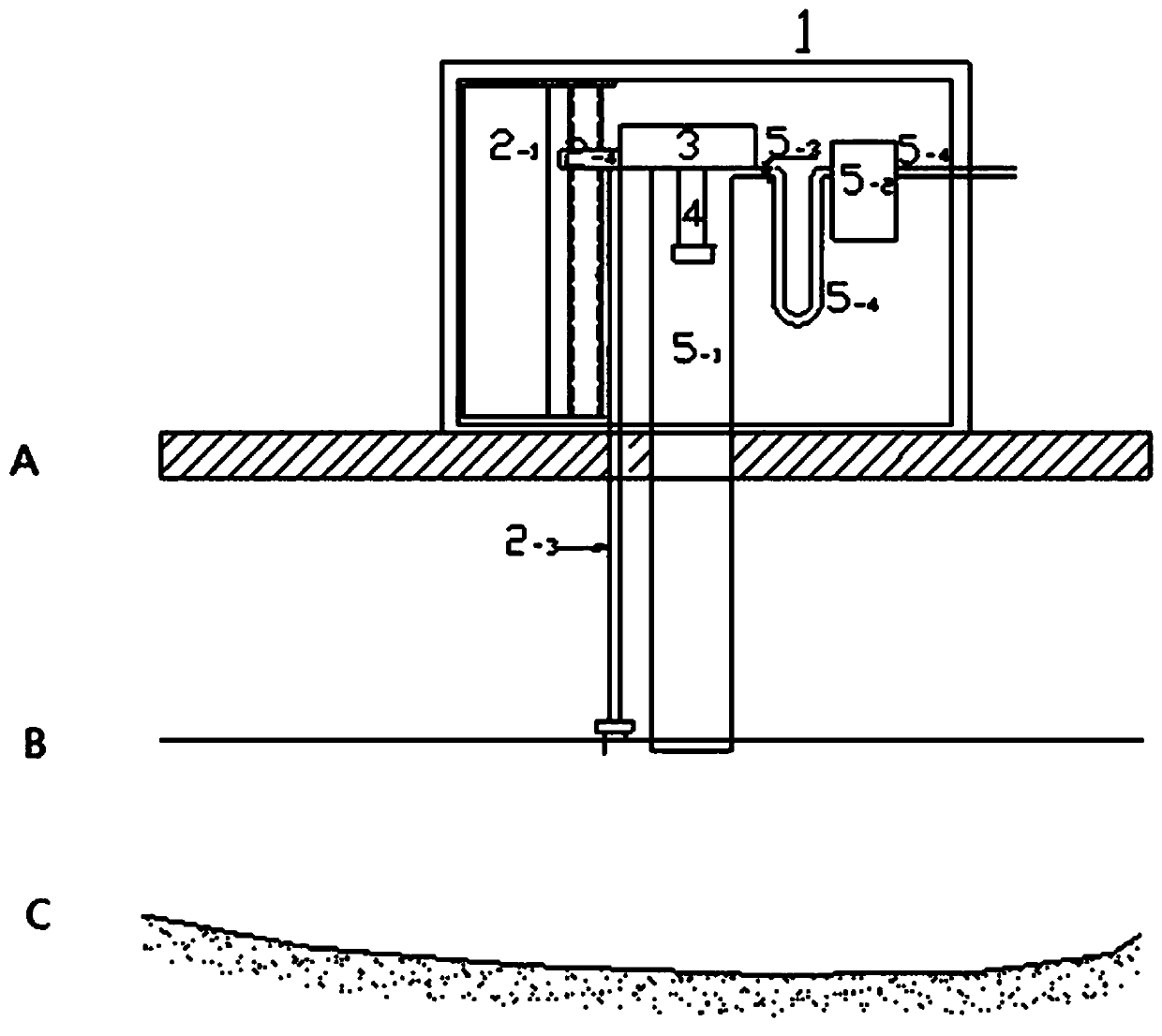
[0039] Embodiment 1, real-time topographic measurement method and measuring instrument of vacuum combined dynamic cement sand model, refer to figure 1 , figure 2 . Measuring instrument, adopt ultrasonic sounder 4 as the water depth measurement system in this instrument, described ultrasonic sounder 4 is arranged in the connecting pipe 5-1, and this connecting pipe 5-1 passes through valve 5-3, exhaust ( Drainage) hose 5-4 is connected with vacuum pump 5-2; This connecting pipe 5-1 is vertically arranged with water surface, and is fixed on the connection device 3; The nut 2- of the lifting device of described connection device 3 and water level detection instrument 4 fixed connection. The nut 2-4 is fixedly connected with the water level detection device 2-3, and the water level detection device 2-3 is composed of a connecting rod and a measuring needle; the water level detection device 2-3 is composed of an electric bridge, a motor and an encoding Disc 2-1 Drive and Contro...


PUM


Abstract

The invention discloses a vacuum combined-type dynamic water silt model real-time landform measurement method and instrument, and the method comprises the steps: (1), determining a distance D1 from an ultrasonic detector to a communicating pipe bottom; (2), determining a distance D2 between a probe of a tracking-type water gauge and the communicating pipe bottom; (3), starting the tracking-type water gauge, starting a vacuum pump when the probe makes contact with a water surface, extracting air from a communicating pipe, and filling the pipe with water; (4), starting the ultrasonic detector; (5), recording the water levels QUOTE tau(t) tau(t) and water depths QUOTE Z' (t) Z' (t) at different moments at the same time, wherein the obtained water depth during ultrasonic measurement subtracts (D1-D2) is QUOTE (shown in the description); (6), calculating the water level and the riverbed landform changes. The method solves the following problems on the basis of the ultrasonic measurement technology: (1), reducing or eliminating the measurement blind region of the instrument; (2), achieving the landform measurement under a condition of a small water depth; (3), reducing or eliminating the impact of the instrument on a flow field and landform changes under the condition of dynamic water; (4), improving the landform measurement precision.

Description

technical field [0001] The invention relates to a real-time terrain measurement method of a vacuum combined dynamic cement-sand model, and also relates to a measuring instrument used in the real-time topographic measurement method of the vacuum combined dynamic cement-sand model. Background technique [0002] At present, three methods are mainly used for topographic measurement of water and sand physical model tests. The first method is to discharge the water body in the model after the test is over, and measure the topography with a stylus, ultrasonic, laser, etc., which is referred to as the dry measurement method; the second method is to stop the model test and maintain a certain water depth, and use ultrasonic (or other) The third method is to use ultrasonic technology to measure under the test conditions of dynamic water, which is referred to as the dynamic water measurement method. [0003] Although the topographic data obtained by method 1 (dry survey method) is rela...

Claims


Application Information

Patent Timeline
Patent Type & Authority Patents(China)
IPC IPC(8): G01M10/00
CPCG01M10/00
Inventor 应强高祥宇琚烈红陈黎明杨氾李蓝汐段子冰杨红左其华
Owner NANJING HYDRAULIC RES INST
Why Eureka
Try Eureka