Large-displacement oil-water separator for gas holder

An oil-water separator and drainage technology, which are applied in liquid separation, separation methods, gas/liquid distribution and storage, etc., can solve the problems of wasting water and lowering the calorific value of gas, saving cooling water, increasing the calorific value of gas, Low cost of use

Active Publication Date: 2011-02-16
CISDI ENG CO LTD
View PDF4 Cites 14 Cited by
  • Summary
  • Abstract
  • Description
  • Claims
  • Application Information

AI Technical Summary

Problems solved by technology

However, when the temperature of the gas is lowered, the calorific value of the gas is relatively low, and a large amount of water is wasted.

Method used


Image

  • Large-displacement oil-water separator for gas holder
  • Large-displacement oil-water separator for gas holder
  • Large-displacement oil-water separator for gas holder

Examples


Embodiment Construction

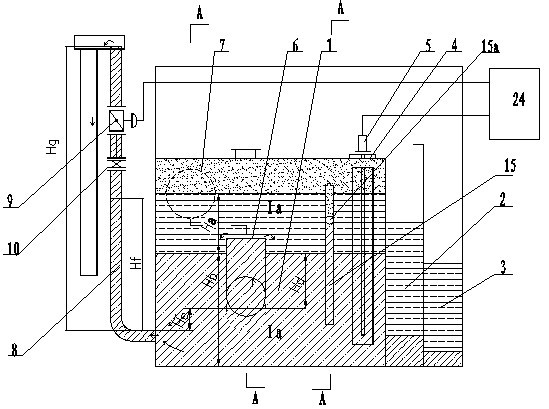
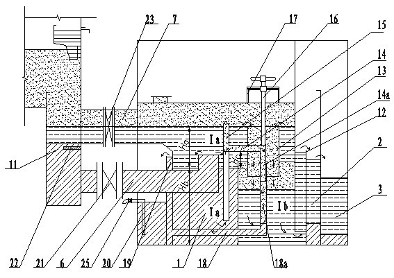
[0020] figure 1 It is a structural schematic diagram of the present invention, figure 2 for figure 1 A cross-sectional view along the direction of A-A-A-A, as shown in the figure: the large displacement oil-water separator of the gas cabinet in this embodiment includes a sealed separation chamber 1, a secondary separation chamber 2 and a recovery chamber 3, and the sealed separation chamber 1 communicates with the oil ditch 11 at the bottom of the gas cabinet , as shown in the figure, communicated through the connecting pipe 7 with valve 23; the sealed separation chamber 1 is divided into an oil-gas-water zone Ia and an oil-gas zone Ib through an overflow device, and the oil-gas zone Ib is located at the lower part of its oil level and the secondary separation chamber 2 are communicated, and the secondary separation chamber 2 is communicated with the recovery chamber 3, which can be communicated through a communication hole, a communication pipe or an overflow; it also inclu...


PUM


Abstract

The invention discloses a large-displacement oil-water separator for a gas holder. A main drainage system comprising a main drainage pipe and a liquid level detection component is arranged on the basis of the conventional oil-water separator. The separator can increase displacement, maintain an extremely small water level change of a bottom oil groove and realize the aim of controlling the oil level of the piston oil groove by using the oil-water separator, thus the separator is suitable for storing the gas with relatively high temperature, improves the heat value of the gas, saves the cooling water and ensures low use cost; and by increasing limited investment, the separator of the invention can greatly improve the drainage capability of the conventional oil-water separator, reduce the loss of the sealing oil and expand the application range of the thin-oil sealed type gas holder from the normal-temperature saturated gas to the gas holder of saturated gas with inlet temperature of about 70 DEG C and is connected in series with the gas pipeline.

Description

technical field [0001] The invention relates to an accessory device of a gas cabinet, in particular to an oil-water separator for sealing circulating oil in a gas cabinet. Background technique [0002] The gas cabinet is a steel container for storing industrial and civil gas. Because it holds gas, it has high requirements for its sealing performance. In the prior art, thin oil-sealed piston-type dry-type gas holders are more commonly used, and sealing oil is continuously supplied to the piston oil groove by means of closed-circuit forced circulation of sealing oil to maintain the height of the oil groove oil seal and prevent gas from escaping. The oil supply device includes an oil supply pump and piping, a reserve oil tank, an overflow device and an oil collecting plate on the piston, which together form a piston sealing oil supply device to supply oil to the piston oil groove to ensure the sealing oil level of the piston oil groove. [0003] During use, since the circulati...

Claims


Application Information

Patent Timeline
Patent Type & Authority Applications(China)
IPC IPC(8): B01D17/025F17B1/02
CPCB01D17/0214B01D19/0063
Inventor 高海平王苏林戴连鹏朱斯郑晓虎
Owner CISDI ENG CO LTD
Why Eureka
Try Eureka