
Image shift compensation calculation method based on elliptical orbit

An elliptical orbit and calculation method technology, applied in the field of aerospace, can solve the problem that the image motion compensation model cannot compensate for the image motion of the elliptical orbit, and achieve the effect of ensuring the accuracy of image motion compensation

Active Publication Date: 2017-12-15
CHANGCHUN INST OF OPTICS FINE MECHANICS & PHYSICS CHINESE ACAD OF SCI
View PDF9 Cites 0 Cited by
  • Summary
  • Abstract
  • Description
  • Claims
  • Application Information

AI Technical Summary

Problems solved by technology

[0003] In order to solve the problem that the existing image motion compensation model cannot realize the compensation of the image motion of the elliptical orbit, the present invention provides an image motion compensation calculation method based on the elliptical orbit

Method used


Image

  • Image shift compensation calculation method based on elliptical orbit
  • Image shift compensation calculation method based on elliptical orbit
  • Image shift compensation calculation method based on elliptical orbit

Examples


specific Embodiment approach 1

[0016] Specific implementation mode 1. Combination Figure 1 to Figure 4 To describe this embodiment,

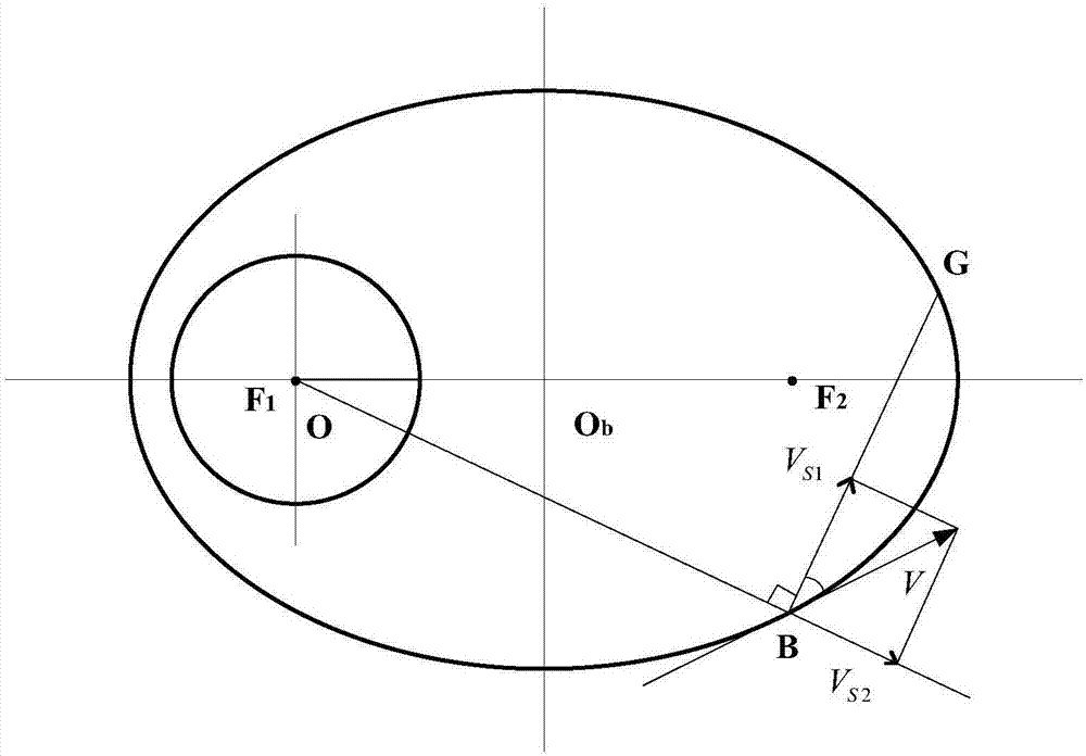
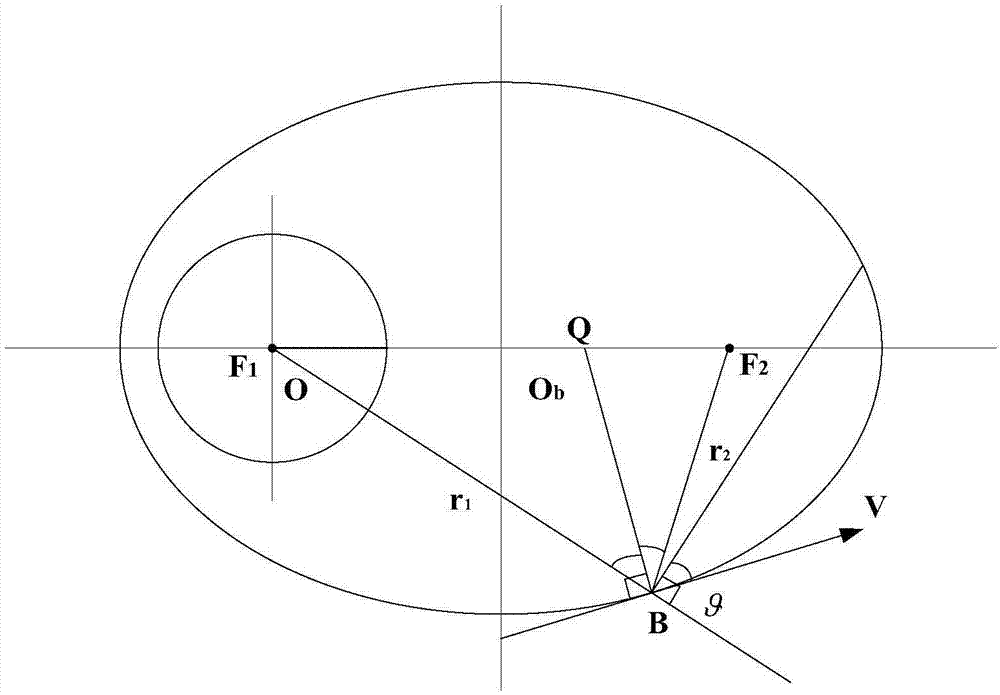
[0017] Step 1. Based on the calculation model of the image motion velocity vector of the near-circular orbit, the image motion velocity vector model of the elliptical orbit is established, such as figure 1 Shown; O is the center of the planet, O b is the orbital center, F 1 and F 2 are the two foci of the ellipse, and B is the position of the spacecraft at a certain moment. During the imaging process, the spacecraft was kept pointing towards the center of the planet. V is the orbital velocity of the spacecraft at this moment, tangent to the orbit, and the optical axis of the camera is along BF 1 The direction points to the center of the planet, and BG is the integral direction of the TDI CCD on the focal plane;

[0018] Step 2. Calculation of elliptical orbital velocity. According to the vitality formula of ellipsoidal motion, the elliptical orbital velocity can be obt...


PUM


Abstract

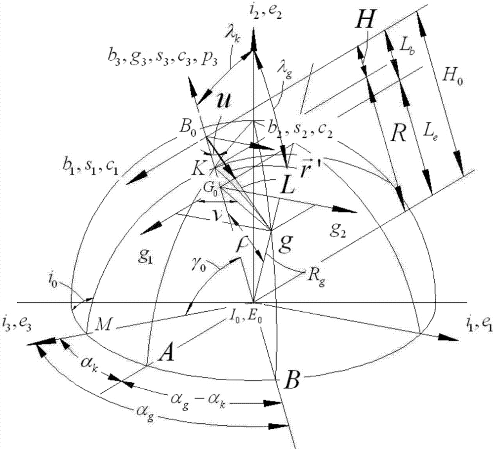
The invention discloses an image shift compensation calculation method based on an elliptical orbit, which relates to the aerospace field and aims at solving the problem that the existing image shift compensation model can not realize compensation on the image shift of the elliptical orbit. Based on a circular orbit image shift speed vector calculation model and parameters of the elliptical orbit, an image shift speed vector model for the elliptical orbit is built, and the elliptical motion orbit speed of a spacecraft, the perigee orbit speed and the apogee orbit speed are calculated; the included angle between the orbit speed and a centrifugal speed is calculated, the circular speed and the centrifugal speed can be acquired according to the calculated included angle, and the elliptical orbit height is calculated; the image shift speed converted by the circular speed of the spacecraft to an image plane passes through a scenic spot sub-satellite vertical horizontal coordinate system, a planetary coordinate system, a planetary inertial coordinate system, an orbit coordinate system, a camera coordinate system and an image plane coordinate system; and the image shift speed of the scenic spot on the image plane of the camera is acquired, and the elliptical orbit image shift is compensated according to the acquired image plane image shift speed.

Description

technical field [0001] The invention relates to the aerospace field, in particular to a calculation method for image motion compensation based on an elliptical orbit. Background technique [0002] The existing image motion compensation model is based on the near-circular orbit of the earth, which is not fully suitable for the elliptical orbit of deep space exploration such as Mars. There is a big difference between the change law of the image motion velocity vector of the elliptical orbit and the near circular orbit: first, the addition of centrifugal velocity (velocity component of the aircraft pointing to the zenith in the orbital plane) makes the change of image motion more complicated, and must be used Real-time calculation of image motion speed, real-time image motion matching, and control of the cumulative error of image motion speed within the allowable range can ensure clear imaging. Second, when imaging at a non-sub-satellite point, the centrifugal velocity will be...

Claims


Application Information

Patent Timeline
IPC IPC(8): G05D1/08
CPCB64G1/244
Inventor 闫得杰王征何云丰曹小涛王栋
Owner CHANGCHUN INST OF OPTICS FINE MECHANICS & PHYSICS CHINESE ACAD OF SCI
Learn More