Ultrasonic vibration auxiliary milling force modeling method based on finite element simulation

A technology of ultrasonic vibration and modeling methods, applied in design optimization/simulation, instruments, electrical digital data processing, etc., can solve problems such as complex models, high calculation costs, and inaccurate simulations

Pending Publication Date: 2021-11-26
DALIAN UNIV OF TECH
View PDF0 Cites 2 Cited by
  • Summary
  • Abstract
  • Description
  • Claims
  • Application Information

AI Technical Summary

Problems solved by technology

However, the 2D milling simulation is too simplified and the simulation is inaccurate, while the 3D milling simulation has the problems of complex models and high calculation costs
At present, for ultrasonic vibration assisted milling, no scholars have combined finite element simulation and traditional modeling, and the existing milling force models have great limitations

Method used


Image

  • Ultrasonic vibration auxiliary milling force modeling method based on finite element simulation
  • Ultrasonic vibration auxiliary milling force modeling method based on finite element simulation
  • Ultrasonic vibration auxiliary milling force modeling method based on finite element simulation

Examples


Embodiment Construction

[0038] In order to make the purpose, technical solutions and advantages of the embodiments of the present invention clearer, the technical solutions in the embodiments of the present invention will be clearly and completely described below in conjunction with the accompanying drawings in the examples of the present invention. , embodiment:

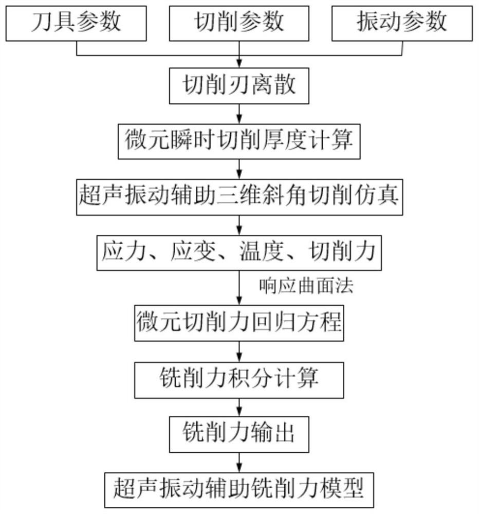
[0039] The technical route of the present invention is as figure 1 shown

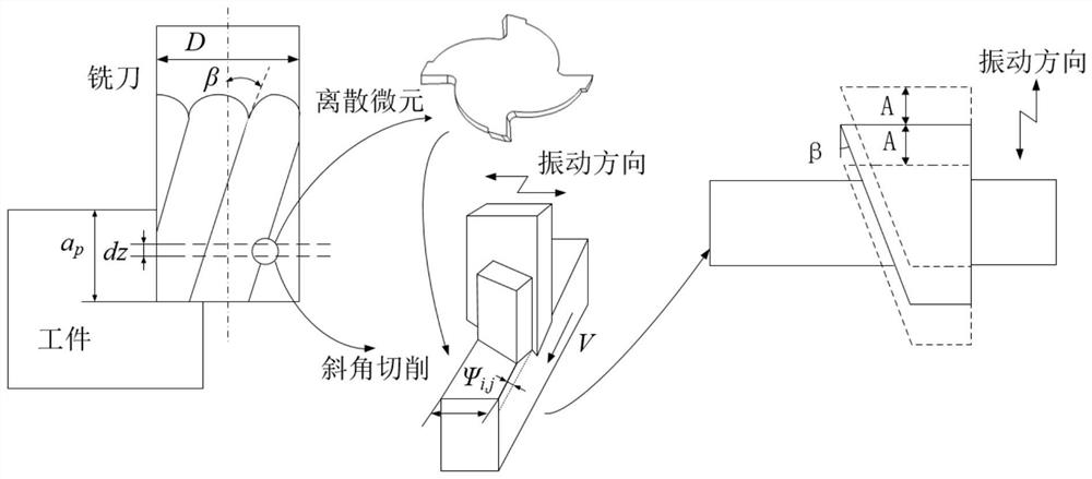
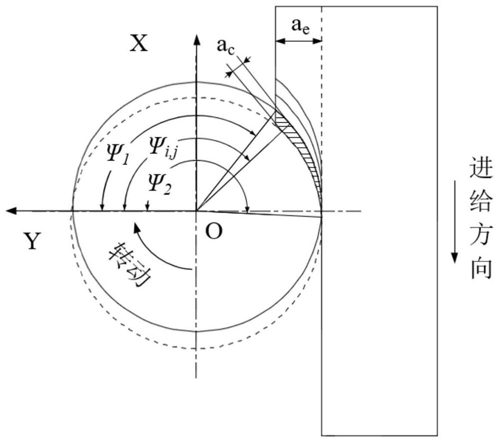
[0040] (1) First determine the parameters of the end mill: the tool radius R is 4mm, the helix angle β is 42°, the number of teeth of the milling cutter is 4; the milling method is down milling; cutting parameters: the spindle speed is 2000r / min, the feed per tooth 0.1mm / r, cutting depth 2mm, cutting width 3mm; ultrasonic vibration parameters: frequency 25000Hz, amplitude 4μm; workpiece material is Ti-6Al-4V. Such as figure 2 As shown, the tool coordinate system is established, the tool feed direction is +X, the direction perpendicular to the feed direction and ...


PUM


Abstract

The invention discloses an ultrasonic vibration auxiliary milling force modeling method based on finite element simulation, which takes tool parameters, cutting parameters and vibration parameters into account, and comprises the following steps: firstly, dispersing a blade into a series of infinitesimal elements along the axial direction, and calculating instantaneous cutting thicknesses of different cutting positions of the infinitesimal elements; then, using a response surface method for designing a simulation scheme about cutter parameters, cutting parameters and vibration parameters, performing a series of bevel angle cutting simulation through ABAQUS, extracting simulation cutting force, and obtaining a regression equation for calculating infinitesimal cutting force; and finally, calculating the cutting force of the infinitesimal at different cutting positions through a regression equation, and performing coordinate transformation and integral summation to obtain a predicted value of the ultrasonic vibration milling force in the milling process. The method can solve the problems that an existing modeling method is long in experimental period and high in experimental cost, and the applicability and reliability of the milling force model are improved.

Description

technical field [0001] The invention relates to an ultrasonic vibration-assisted milling force modeling method based on finite element simulation, which belongs to the field of metal processing. Background technique [0002] Milling is a conventional metal processing method, which is often used to process characteristic structures such as planes, bosses, and cavities. In the field of aviation manufacturing, high-strength, corrosion-resistant alloy materials such as titanium alloys are widely used as structural materials. However, during the milling process of titanium alloys, the tool wear is serious and the surface quality is poor, which restricts aviation technology to a certain extent. development of. Ultrasonic vibration-assisted cutting is a processing technology that applies high-frequency and low-amplitude vibration to the tool or workpiece for cutting. The introduction of ultrasonic vibration can achieve intermittent cutting, thereby obtaining better surface quality...

Claims


Application Information

Patent Timeline
Patent Type & Authority Applications(China)
IPC IPC(8): G06F30/23G06F119/14
Inventor 董志刚康仁科张园王晨旭
Owner DALIAN UNIV OF TECH
Why Eureka
Try Eureka