
A PSF Inverse Transform Method Based on Parallel Lu Decomposition

An inverse transformation and block technology, applied in complex mathematical operations and other directions, can solve problems such as time-consuming, difficult to obtain results, serious time consumption, etc., to reduce time consumption, high memory reuse rate, parallelism high degree of effect

Active Publication Date: 2020-08-04
SHENZHEN GRADUATE SCHOOL TSINGHUA UNIV
View PDF4 Cites 0 Cited by
  • Summary
  • Abstract
  • Description
  • Claims
  • Application Information

AI Technical Summary

Problems solved by technology

However, as the pixel value of the imaging plane increases, the dimension of the equation system will also increase sharply, which makes it difficult to solve the result by using the traditional method of solving the equation system, or the solution process is very complicated and the time consumption is very serious
[0003] Among the existing methods for solving the inverse change of PSF: one is to directly solve the inverse matrix of the joint PSF matrix, and multiply the inverse matrix to the left by a constant term to obtain the final result; this scheme is relatively intuitive in theory, and the steps are relatively simple. But it takes a lot of time, and the computer's memory and CPU requirements are also high during the solution process; the other type is based on the left division function that comes with MATLAB. This solution takes a short time and is more intuitive in theory, but it is suitable for platforms. It is relatively limited, and the scalability of the code package is poor, the solution speed is limited, and the calculation efficiency is poor

Method used


Image

  • A PSF Inverse Transform Method Based on Parallel Lu Decomposition
  • A PSF Inverse Transform Method Based on Parallel Lu Decomposition
  • A PSF Inverse Transform Method Based on Parallel Lu Decomposition

Examples


Embodiment Construction

[0047] The present invention will be further described below with reference to the accompanying drawings and in combination with preferred embodiments.

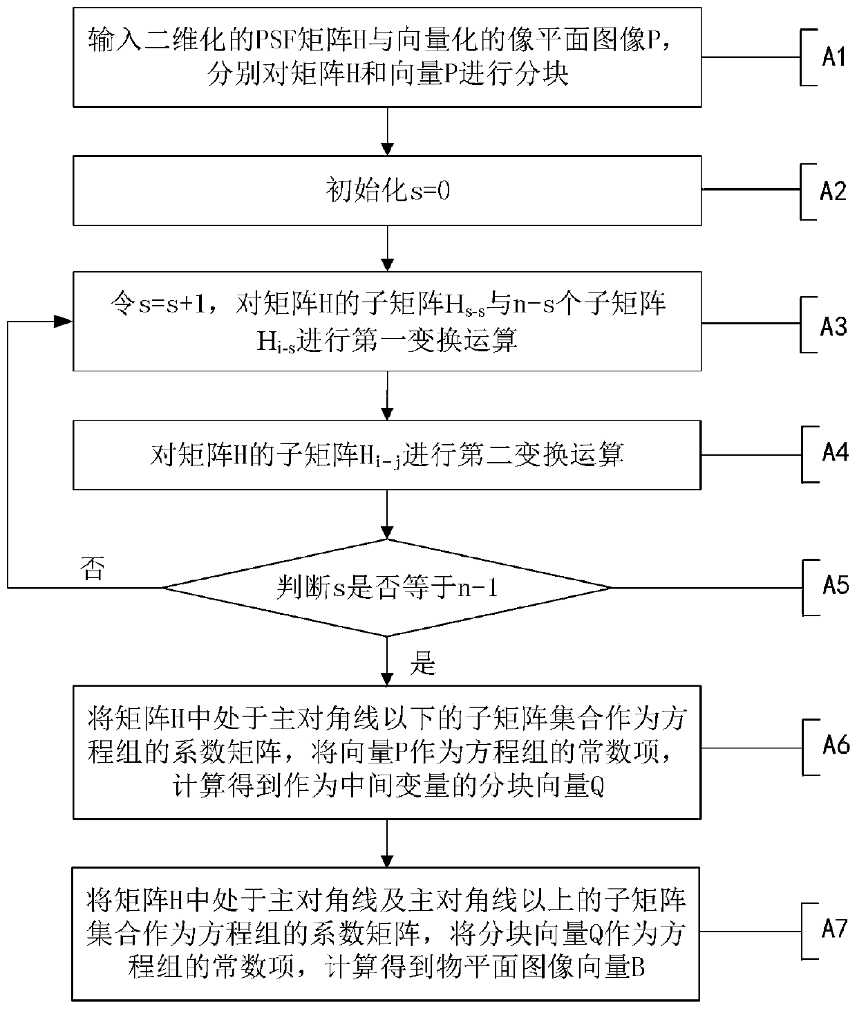
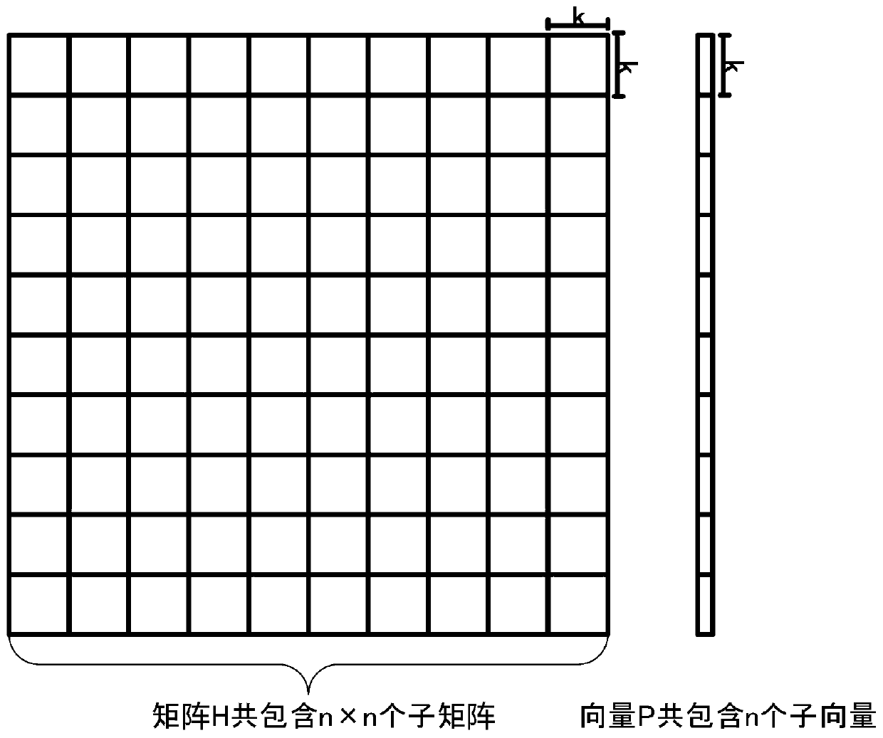
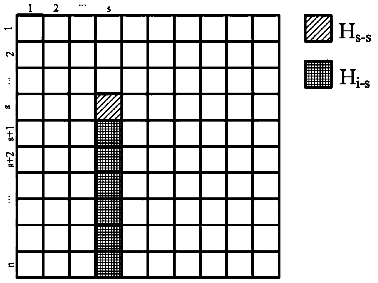
[0048] In order to improve the efficiency of PSF inverse transformation, try to keep the scalability of the algorithm, such as figure 1As shown, the preferred embodiment of the present invention discloses a PSF inverse transformation method based on parallel LU decomposition. The idea of ​​the present invention is based on the convenience of LU decomposition in solving linear equations, and utilizes the method of matrix partitioning to make LU It is possible to use parallel processing in the decomposition, and use parallelized LU decomposition technology and Gaussian elimination method to effectively reduce the time consumed by PSF inverse transformation; specifically, the following steps are included:

[0049] A1: Input the two-dimensional joint PSF matrix H and the vectorized image plane image P, respectively block the matr...


PUM


Abstract

The invention discloses a PSF inverse transformation method based on parallel LU decomposition. The PSF inverse transformation method comprises the steps of A1, inputting a two-dimensional PSF matrix H and a vectorized image planar image P and blocking the matrix H and the vector P respectively; A2, initializing s=0; A3, making s=s+1 and conducting first transformation computation on a submatrix Hs-s of the matrix H and n-s submatrixes Hi-s; A4, conducting second transformation computation on a submatrix Hi-j of the matrix H; A5, judging whether s is equal to n-1 or not, if yes, executing the step A6, and if not, repeating the step A3; A6, using a submatrix set below a main diagonal in the matrix H as an equation set coefficient matrix, using the vector P as an equation set constant item, conducting calculation to obtain a blocked vector Q and using the blocked vector Q as a middle variable; A7, using a submatrix set at a main diagonal or above in the matrix H as an equation set coefficient matrix, using the blocked vector Q as an equation set constant item, and conducting calculation to obtain an object planar image vector B. According to the PSF inverse transformation method based on the parallel LU decomposition, the time consumed in the PSF transformation process can be effectively shortened.

Description

technical field [0001] The invention relates to the fields of computer vision and digital image processing, in particular to a PSF inverse transformation method based on parallel LU decomposition. Background technique [0002] In recent years, light field images captured by light field cameras have aroused widespread attention in computer vision fields such as stereo display, 3D reconstruction, and virtual reality. The modeling and analysis of light field cameras has also become a research focus. According to Fresnel Diffraction theorem, the theoretical model of a light field camera can often be corresponded to a linear equation system, where the coefficient matrix of the equation system is the two-dimensional joint PSF (point spread function) matrix, and the unknown quantity of the equation system is vectorized The object plane image information, the constant term of the equation system is the vectorized imaging plane image information. The purpose of PSF inverse transform...

Claims


Application Information

Patent Timeline
Patent Type & Authority Patents(China)
IPC IPC(8): G06F17/16
CPCG06F17/16
Inventor 金欣李钏溥戴琼海
Owner SHENZHEN GRADUATE SCHOOL TSINGHUA UNIV
Learn More