
Stirring device with convenient-to replace stirring shaft

A technology for convenient replacement and stirring devices, applied in the direction of mixers with rotating stirring devices, mixer accessories, transportation and packaging, etc., can solve the problems of difficulty in meeting various use needs, single structure, and many processes, and achieve suitable promotion and use , Guaranteed operation effect, easy to use effect

Inactive Publication Date: 2017-12-19
王俊哲
View PDF5 Cites 11 Cited by
  • Summary
  • Abstract
  • Description
  • Claims
  • Application Information

AI Technical Summary

Problems solved by technology

A mixer is a mixer. Because the usual function of a mixer is to mix and mix various types of dry powder mortar, it is commonly called a mixer. The existing mixing device has a single structure. In the process of use, only a single mixing blade is often used, which is difficult to meet in practice. Due to the various usage requirements in the operation, it is necessary to replace the mixing drum for the next step of operation. Too many processes are very troublesome.

Method used


Image

  • Stirring device with convenient-to replace stirring shaft
  • Stirring device with convenient-to replace stirring shaft
  • Stirring device with convenient-to replace stirring shaft

Examples


Embodiment Construction

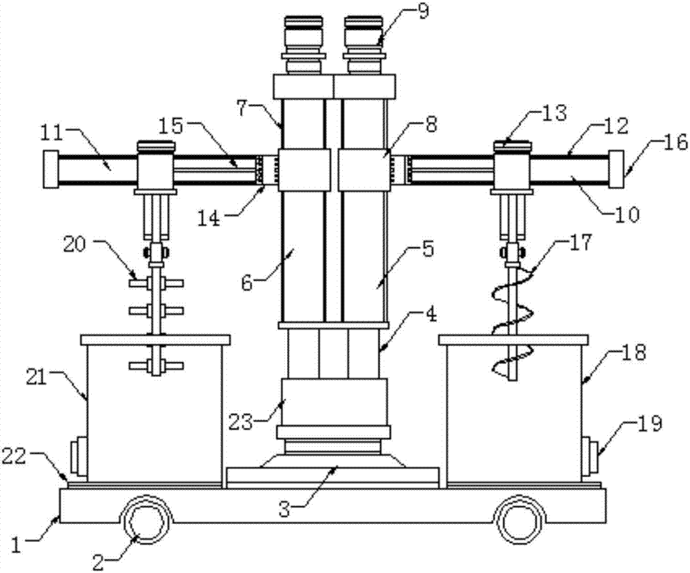
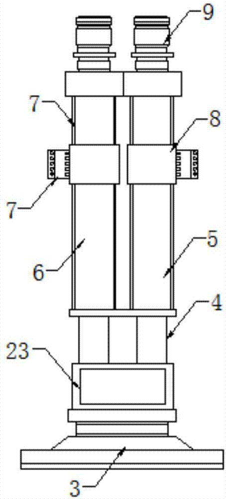
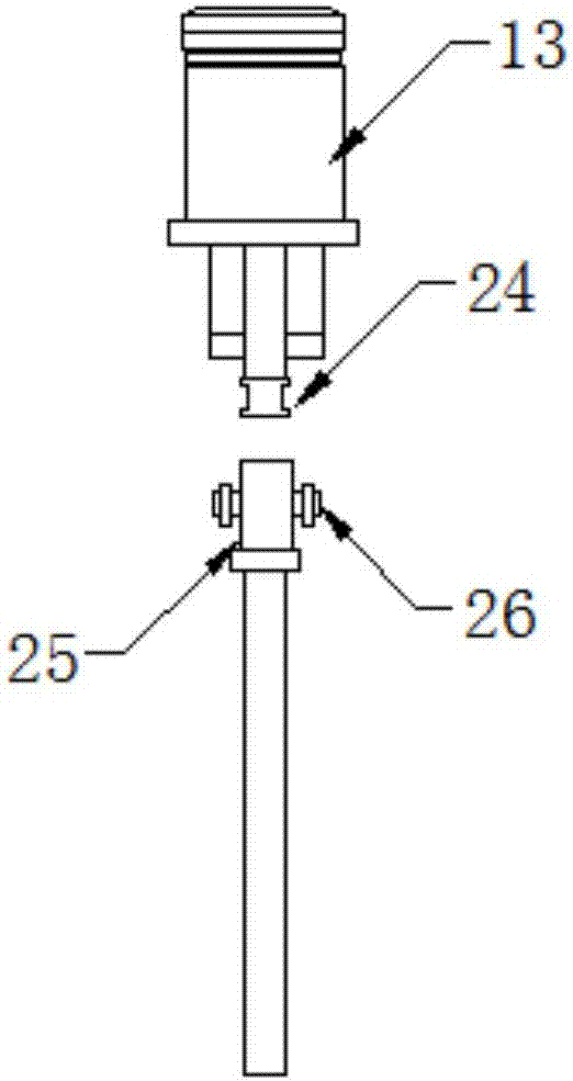
[0021] Such as Figure 1-3 As shown, this specific embodiment adopts the following technical solutions: including support base plate 1, roller 2, rotating base 3, jacking rod 4, first bracket 5, second bracket 6, longitudinal slide rail 7, lifting slide seat 8, lifting Motor 9, first beam 10, second beam 11, transverse slide rail 12, stirring motor 13, transverse cylinder 14, telescopic rod 15, limit end cap 16, first stirring shaft 17, first stirring drum 18, discharge port 19, the second stirring shaft 20, the second mixing drum 21, the chute 22, the hydraulic cylinder 23, the positioning joint 24, the limit interface 25 and the limit pin 26, the support base 1 is fixedly installed with a rotating base 3, and the rotating base 3 is fixedly installed with a hydraulic cylinder 23, and the output end of the hydraulic cylinder 23 is movably connected with the first support 5 and the second support 6 through the jacking rod 4, and the first support 5 and the second support 6 are ...


PUM


Abstract

The invention discloses a stirring device with a convenient-to replace stirring shaft. The stirring device comprises a supporting bottom plate, wherein a rotary base is fixedly mounted on the supporting bottom plate; a hydraulic cylinder is mounted on the rotary base; the hydraulic cylinder is movably connected with a first bracket and a second bracket through a jacking rod; the first bracket and the second bracket are arranged correspondingly; longitudinal sliding rails are arranged on the first bracket and the second bracket; hoisting sliding seats are mounted on the first bracket and the second bracket in a sliding manner through the longitudinal sliding rails; hoisting motors are mounted at the tops of the first bracket and the second bracket; output ends of the hoisting motors are fixedly connected with the hoisting sliding seats through lifting chains. The stirring device with the convenient-to replace stirring shaft is compact in structure and convenient to use; up-down movement of the brackets is realized through the hydraulic cylinder, and the stirring shaft is replaced in a working process according to actual conditions; the stirring device has high working efficiency and relatively high practicability, ensures the working effect and is adaptive to various different working modes; the stirring device is high in stability and high in precision, and the utilization of manpower is effectively reduced.

Description

Technical field: [0001] The invention relates to the technical field of stirring equipment, in particular to a stirring device for convenient replacement of a stirring shaft. Background technique: [0002] A mixer is a machine with a bladed shaft that rotates in a cylinder or a tank to stir and mix various raw materials to make it a mixture or a suitable consistency. There are many kinds of mixers, such as forced mixers, single-shaft mixers, twin-shaft mixers, etc. Note: The mixer and automatic feeder must be cleaned inside, especially in winter, which can prolong the life. A mixer is a mixer. Because the usual function of a mixer is to mix and mix various types of dry powder mortar, it is commonly called a mixer. The existing mixing device has a single structure. In the process of use, only a single mixing blade is often used, which is difficult to meet in practice. Due to various usage requirements in the operation, it is necessary to replace the mixing drum for the next...

Claims


Application Information

Patent Timeline
Patent Type & Authority Applications(China)
IPC IPC(8): B01F7/18B01F7/24B01F13/10
CPCB01F27/0541B01F27/114B01F27/074B01F27/112B01F27/191B01F27/2322B01F27/92B01F33/501B01F33/813B01F27/90B01F35/3215B01F35/3204
Inventor 王俊哲
Owner 王俊哲
Learn More