Communication-in-motion antenna cosine scanning inertial navigation course correction method

A technology of cosine scanning and navigation direction, which is applied in the field of satellite communication, can solve the problems of poor satellite pointing accuracy of the antenna system, the heading angle does not meet the Shura oscillation cycle, and the accumulation of large heading angle errors, so as to achieve small click disturbance and reduce control Complexity, the effect of compensating for smoothness

Active Publication Date: 2017-12-19
SHANDONG INST OF AEROSPACE ELECTRONICS TECH
View PDF5 Cites 3 Cited by
  • Summary
  • Abstract
  • Description
  • Claims
  • Application Information

AI Technical Summary

Problems solved by technology

However, the heading angle of the inertial navigation system does not meet the Shura oscillation period, and its error increases with time. During the long-term use of the inertial navigation system, there will be a large error accumulation in the heading angle, which will lead to the continuous deterioration of the satellite pointing accuracy of the antenna system.
Simply relying on the high-precision navigation technology of the inertial navigation system to realize the long-term high-precision satellite signal tracking function of the mobile communication antenna system, the cost is relatively high. How to overcome the disadvantages of the low-cost inertial navigation system that the heading angle error accumulates over time and achieve long-term uninterrupted The high-precision and stable satellite tracking function of the antenna system under running conditions is a difficulty in the current communication system based on the inertial navigation scheme

Method used


Image

  • Communication-in-motion antenna cosine scanning inertial navigation course correction method
  • Communication-in-motion antenna cosine scanning inertial navigation course correction method
  • Communication-in-motion antenna cosine scanning inertial navigation course correction method

Examples


Embodiment Construction

[0027] The present invention will be described in detail below with reference to the accompanying drawings and examples.

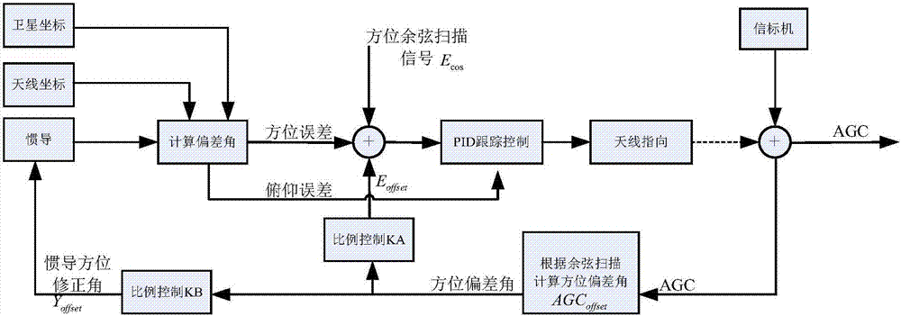
[0028] Such as figure 1 As shown, the inertial navigation direction correction method of the present invention includes the following specific steps:

[0029] Step 1. Initialization: The mobile communication antenna performs 360-degree scanning to find satellites, and completes initialization and aligns with satellites. Then use the satellite signal to reversely calculate the inertial navigation heading angle, and calibrate the inertial navigation heading angle.

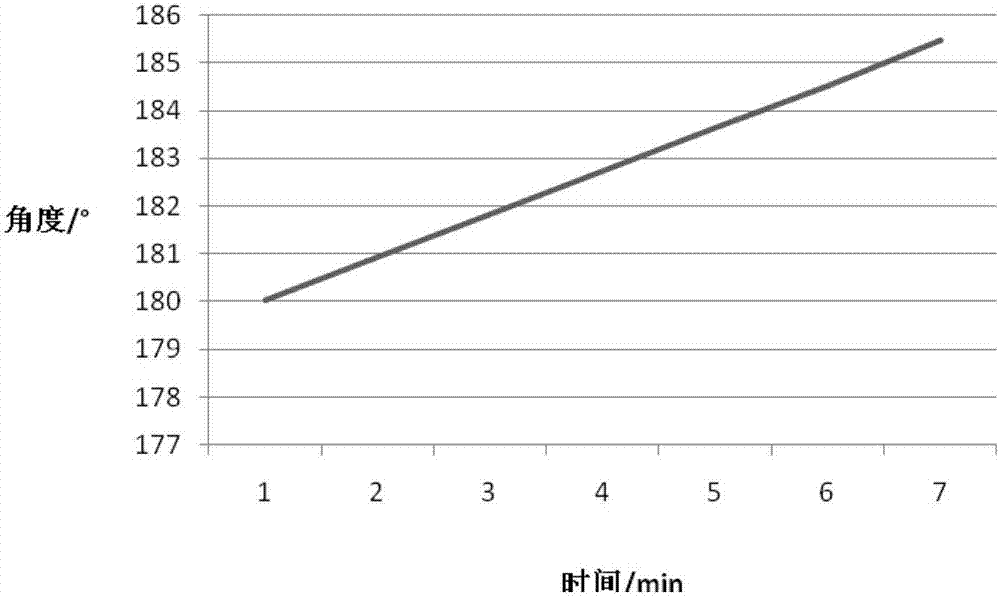
[0030] Step 2. Inertial navigation tracking control: According to the satellite coordinates, antenna coordinates, and inertial navigation attitude data, the azimuth and pitch error angle are calculated, and the antenna tracking control is realized through the PID control algorithm. During the tracking process, due to the drift of inertial navigation, the azimuth of the antenna gradually deviate...


PUM


Abstract

The invention discloses a communication-in-motion antenna cosine scanning inertial navigation course correction method. A cosine scanning method is adopted to search a satellite signal; only rotation of an azimuth axis exists in the method and pitching motion can be omitted, so that control complexity can be lowered; in addition, when a becoming machine is not high in precision, a signal deviation curve is obtained by a circular cone scanning mode, and randomness occurs, so that the method is more suitable for communication-in-motion equipment with not high becoming machine precision, thereby further saving cost; through an AGC signal difference value, the antenna azimuth deviation can be compensated through a proportion control method; a mode adopting the AGC signal maximum value inverse solution navigation course for azimuth compensation is performed; and by adoption of the method, the linear relation between AGC signal cosine scanning left and right difference value and azimuth deviation angles and the optimal linear coefficient can be found, so that a complex calculation process can be omitted; and in addition, through proportional control, compensation can be more stable, and click disturbance can be lower.

Description

technical field [0001] The invention belongs to the technical field of satellite communication, and in particular relates to an inertial navigation direction correction method for antenna cosine scanning in motion, which is suitable for occasions where low-cost inertial navigation requires the system to maintain the accuracy of antenna tracking satellites for a long time. Background technique [0002] Communication in motion is a broadband mobile satellite communication system that uses fixed service satellite resources and antenna systems installed on carriers to establish and maintain satellite links between carriers and target satellites in static and moving states. Its essence is to keep the antenna azimuth, pitch, and polarization three-dimensionally aligned with the satellite at all times while in motion. Under the existing technical conditions, most mobile communication products need expensive attitude and heading reference system AHRS (Attitude and heading reference ...

Claims


Application Information

Patent Timeline
Patent Type & Authority Applications(China)
IPC IPC(8): H01Q3/00
CPCH01Q3/005
Inventor 韩泉城杨志群苗萍石宝民
Owner SHANDONG INST OF AEROSPACE ELECTRONICS TECH
Why Eureka
Try Eureka