A cascaded inverter system

A cascading inverter and cascading technology, applied in AC network circuits, electrical components, single-network parallel feeding arrangements, etc., can solve the problem of high communication connection costs, reduce strong dependencies, avoid high costs, and reduce the number of and the effect of distance

Active Publication Date: 2021-04-13
SUNGROW POWER SUPPLY CO LTD
View PDF9 Cites 0 Cited by
  • Summary
  • Abstract
  • Description
  • Claims
  • Application Information

AI Technical Summary

Problems solved by technology

[0005] The invention provides a cascaded inverter system to solve the problem of high communication connection cost caused by high-speed communication in the prior art

Method used


Image

  • A cascaded inverter system
  • A cascaded inverter system
  • A cascaded inverter system

Examples


Embodiment Construction

[0043] The following will clearly and completely describe the technical solutions in the embodiments of the application with reference to the drawings in the embodiments of the application. Apparently, the described embodiments are only some of the embodiments of the application, not all of them. Based on the embodiments in this application, all other embodiments obtained by persons of ordinary skill in the art without creative efforts fall within the protection scope of this application.

[0044] The invention provides a cascaded inverter system to solve the problem of high communication connection cost caused by high-speed communication in the prior art.

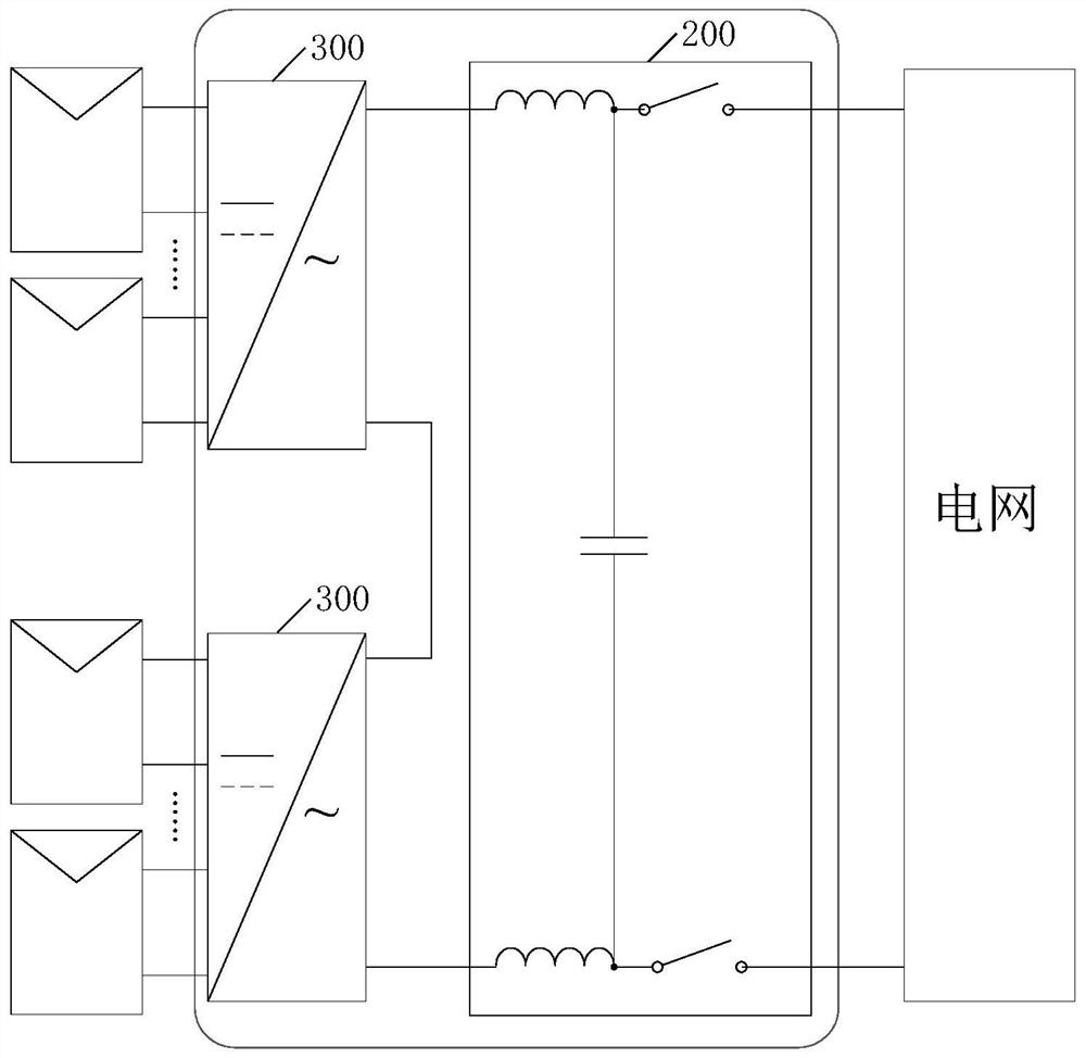
[0045] Specifically, for the cascaded inverter system, see figure 2 , including: a system interface board 200 and multiple multi-input subsystems 300; wherein:

[0046] The output ends of multiple subsystems 300 are cascaded, and the two ends of the cascade are connected to the power grid through the system interface boa...


PUM


Abstract

The invention provides a cascaded inverter system, the output terminals of each multi-input subsystem are cascaded to the system interface board, and the communication unit, detection unit, filter unit, multiple inverter units and at least one control unit in the subsystem The devices are all set in the same box, and the detection and control information of each inverter unit in the same subsystem can be transmitted uniformly through the communication unit. Compared with the existing technology, the distance between the system interface board and each inverter unit is reduced. The number and distance of inter-communication connections greatly reduce the strong dependence on real-time communication, without the need for high-speed communication, thereby avoiding the problem of high cost of communication connections.

Description

technical field [0001] The invention relates to the technical field of photovoltaic power generation, in particular to a cascaded inverter system. Background technique [0002] In the field of photovoltaic power generation, in order to avoid the problem of partial power loss caused by component mismatch due to factors such as shadow shading and differences in photovoltaic module parameters, the existing technology usually adopts figure 1 The scheme of the cascaded H-bridge inverter photovoltaic power generation system with component MPPT function is shown. [0003] see figure 1 , the program uses a conventional control algorithm, the system controller in the system interface board 102, through the received input voltage and current values ​​collected by each H-bridge inverter 101, uses the MPPT algorithm to obtain each H-bridge inverter 101 can output the maximum power command value, and then use the maximum power command value of all H-bridge inverters 101 to obtain the c...

Claims


Application Information

Patent Timeline
Patent Type & Authority Patents(China)
IPC IPC(8): H02J3/38
CPCH02J3/383H02J3/385Y02E10/56
Inventor 顾亦磊王新宇徐君
Owner SUNGROW POWER SUPPLY CO LTD
Why Eureka
Try Eureka