Wafer scrubbing device

A wafer and roller brush technology, applied in electrical components, semiconductor/solid-state device manufacturing, circuits, etc., can solve the problems affecting the stability of the brushing process, poor rigidity of the brushing device, and axial movement of the roller brush shaft. Wafer scrubbing effect, overall rigidity improvement, and the effect of avoiding axial movement

Active Publication Date: 2017-12-22
北京晶亦精微科技股份有限公司
View PDF9 Cites 4 Cited by
  • Summary
  • Abstract
  • Description
  • Claims
  • Application Information

AI Technical Summary

Problems solved by technology

[0006] The purpose of the present invention is to solve the problem that the fixing of the roller brush shaft of the current wafer scrubbing device is mainly tightened by spring force, and the roller brush shaft is prone to axial movement when

Method used


Image

  • Wafer scrubbing device
  • Wafer scrubbing device
  • Wafer scrubbing device

Examples


Embodiment Construction

[0040] The present invention will now be described in detail with reference to the accompanying drawings. These drawings are all simplified schematic diagrams, which only illustrate the basic structure of the present invention in a schematic manner, so they only show the configurations related to the present invention.

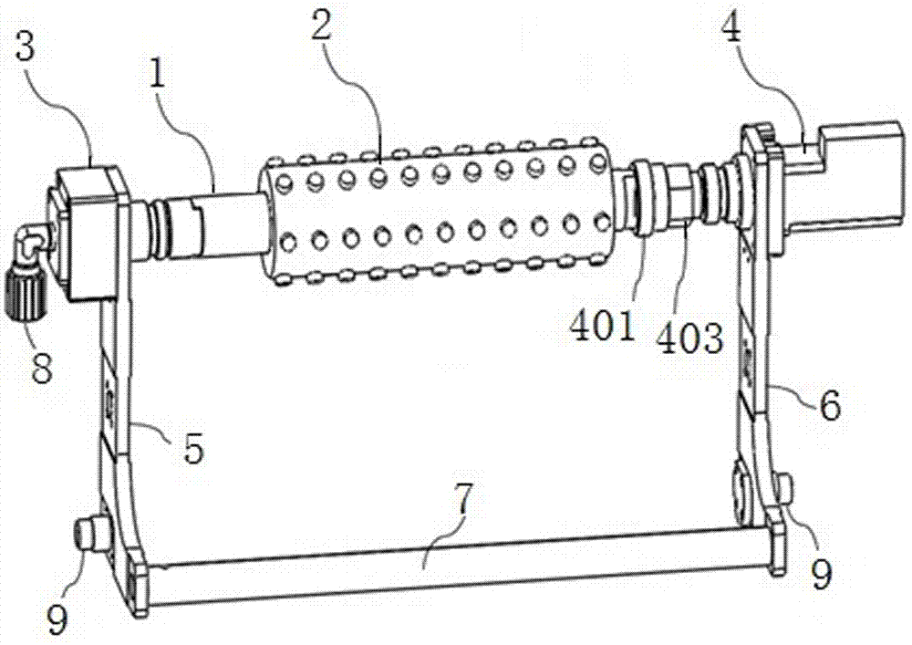
[0041] Such as Figure 1-3d As shown, the wafer scrubbing device of the present invention includes a roller brush shaft 1, a roller brush 2, a water inlet end 3 and a driving end 4;

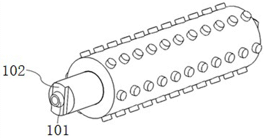
[0042] The roller brush shaft 1 is hollow, and a section of the shaft wall is provided with several small holes, and the roller brush 2 is sleeved on the section of the roller brush shaft 1 provided with small holes and covers all the small holes;

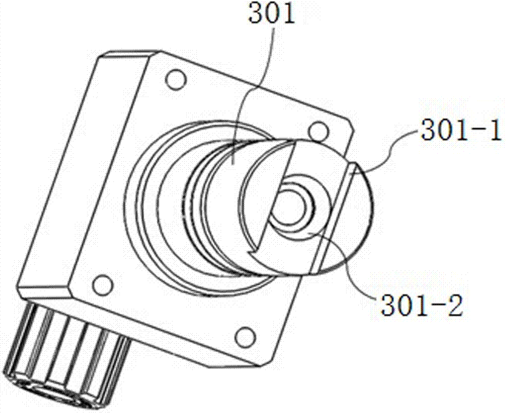
[0043] The water inlet end 3 is connected to the first end of the roller brush shaft 1, and the driving end 4 is connected to the second end of the roller brush shaft 1;

[0044] The water inlet end 3 is supported on the front side ...


PUM


Abstract

The invention discloses a wafer scrubbing device. The wafer scrubbing device comprises a roll brush shaft, a roll brush, a water inlet end and a driving end. The roll brush shaft is hollow, and a plurality of small holes are formed in one section of the shaft wall. The roll brush is arranged on the section, where the small holes are formed, of the roll brush shaft in a sleeving mode and covers the small holes. The water inlet end is connected to a first end of the roll brush shaft. The driving end is connected to a second end of the roll brush shaft. The water inlet end is supported on a front side plate. The driving end is supported on a rear side plate. The bottom end of the front side plate is connected with the rear side plate through a connecting rod. The water inlet end comprises a hollow water inlet end spindle. A first end of the water inlet end spindle is connected to a water inlet pipe joint, and a second end of the water inlet end spindle is connected with the roll brush shaft in a clamped mode. The driving end comprises a driving end spindle. A first end of the driving end spindle is connected with the roll brush shaft through a locking mechanism, and a second end of the driving end spindle is connected to a motor. Through the connecting mode that one end of the roll brush shaft is clamped and the other end of the roll brush shaft is locked, the connection rigidity of the roll brush shaft is greatly improved, axial movement during high-speed rotation is avoided, and the better wafer scrubbing effect is achieved.

Description

technical field [0001] The invention relates to a wafer scrubbing device, which belongs to the field of cleaning wafers after chemical mechanical polishing (CMP). Background technique [0002] The wafer brushing process is an essential part of the post-CMP cleaning process. Its principle is to remove particles attached to the wafer surface through the friction between the roller brush and the wafer. Patent No. 200480031861.0's invention patent "Scrubbing Machine and Scrubbing Cabinet" discloses a typical wafer scrubbing box. The shafts are located on both sides of the wafer. One end of the brushing shaft is connected to the water inlet module, which is responsible for injecting pure water into the roller brush shaft to keep the roller brush wet; the other end is connected to the driving module, and the motor drives the roller brush to rotate. When the wafers are in contact, the rotation generates friction to remove particles from the wafer surface. The two left and right s...

Claims


Application Information

Patent Timeline
IPC IPC(8): B08B1/02H01L21/67
CPCB08B1/002B08B1/02H01L21/67011
Inventor 史霄陶利权田洪涛舒福璋熊朋
Owner 北京晶亦精微科技股份有限公司
Why Eureka
Try Eureka