
Thermal load simulation and error detection system and method for machine tool cutting process

A technology of cutting processing and load simulation, applied in the direction of metal processing equipment, metal processing machinery parts, manufacturing tools, etc., can solve the problems of increased cutting force, large cutting force, and processing errors, so as to reduce processing errors and improve The effect of machining accuracy

Active Publication Date: 2019-07-02
NANJING UNIV OF AERONAUTICS & ASTRONAUTICS
View PDF6 Cites 0 Cited by
  • Summary
  • Abstract
  • Description
  • Claims
  • Application Information

AI Technical Summary

Problems solved by technology

However, in machining where the cutting depth and cutting amount are gradually increased, the cutting force is undoubtedly increased a lot, and difficult-to-cut materials gradually occupy a place in machining. For these materials with poor cutting performance, a large cutting force will occur. force, resulting in machining errors
[0006] During machine tool cutting, affected by the rotation of the spindle, the movement of the feed mechanism and chips, geometric detection devices such as laser interferometers and laser displacement sensors cannot be installed on the machine tool, and the errors caused by various loads on the machine tool cannot be measured online. Through The method of simulating loading of various loads of the machine tool to simulate the actual working conditions of the machine tool and then performing error detection is generally only aimed at the force (moment) load of the machine tool. In the current research, no precedent for simulated loading of the thermal load of the machine tool has been found.

Method used


Image

  • Thermal load simulation and error detection system and method for machine tool cutting process
  • Thermal load simulation and error detection system and method for machine tool cutting process
  • Thermal load simulation and error detection system and method for machine tool cutting process

Examples


Embodiment Construction

[0051]In order to clarify the functions and effects that can be realized by the device of the present invention, the specific implementation of the device will be described in detail below in conjunction with the accompanying drawings.

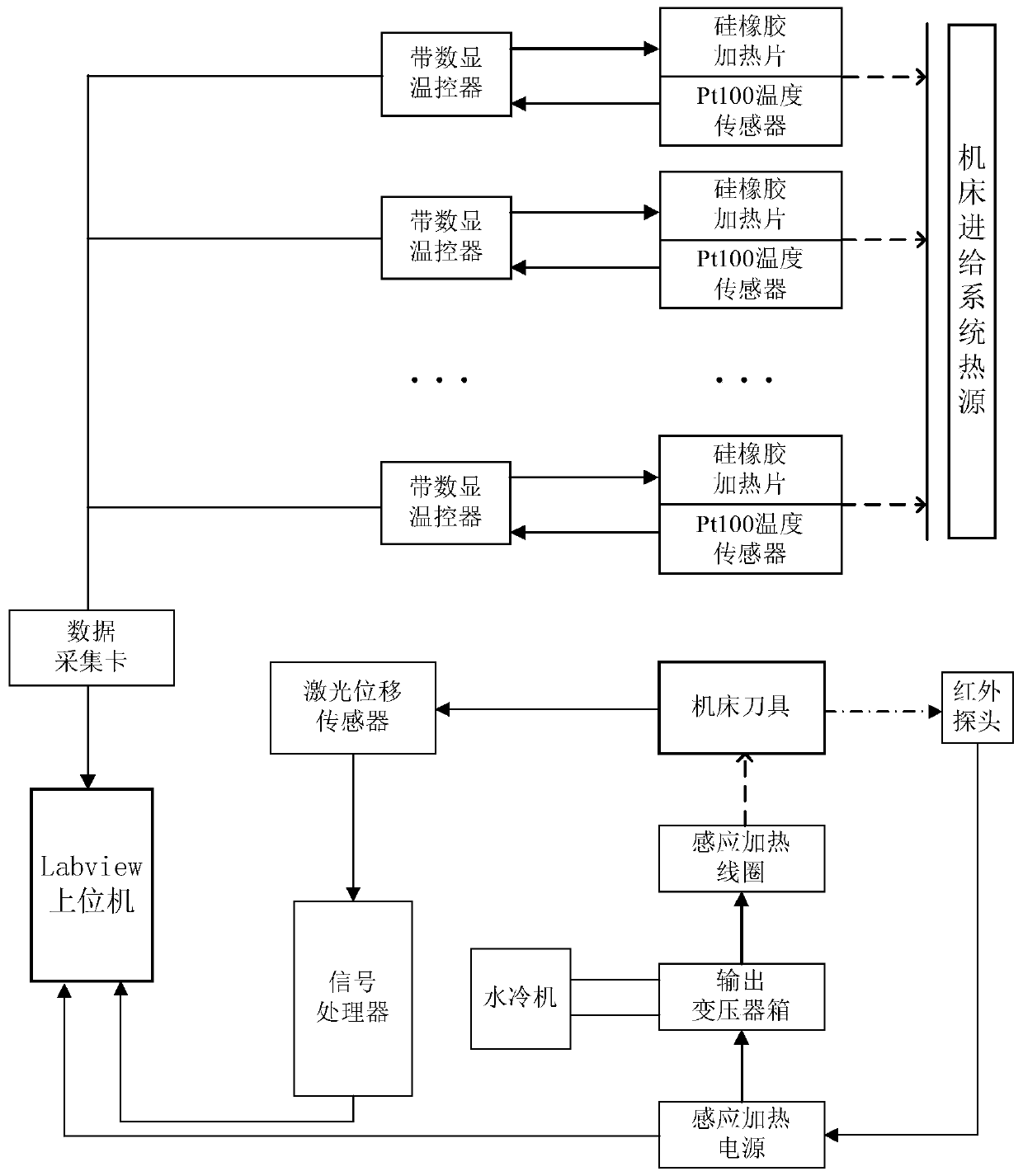
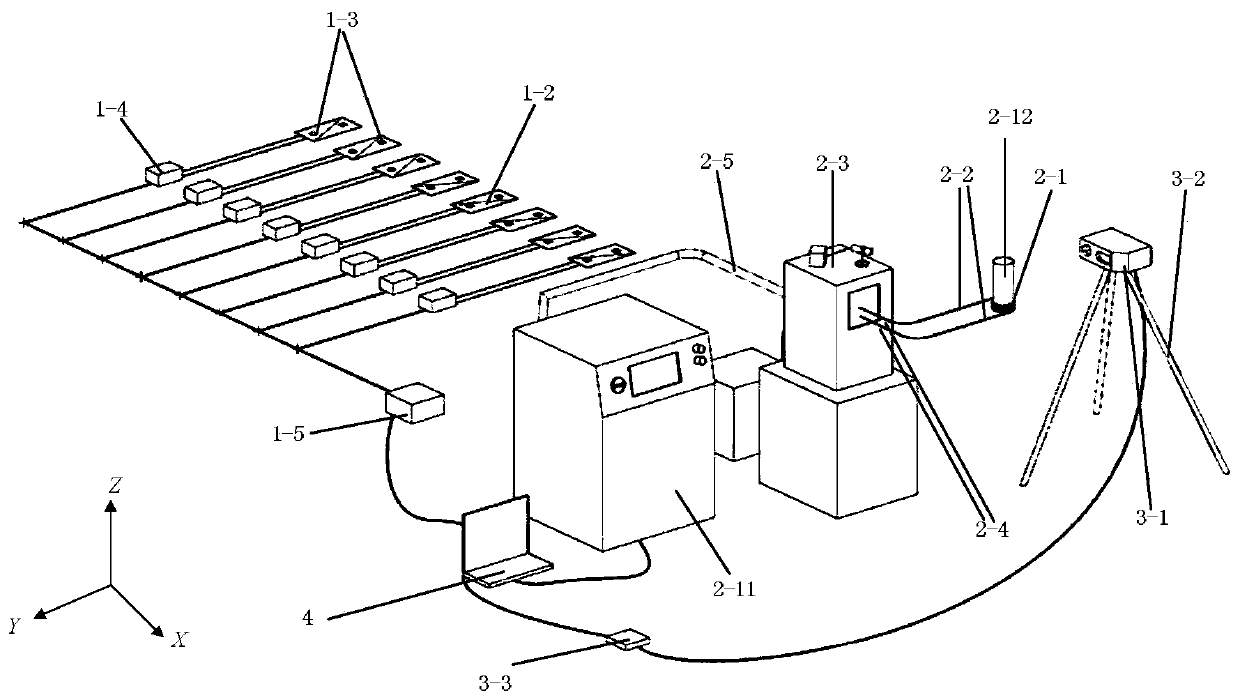
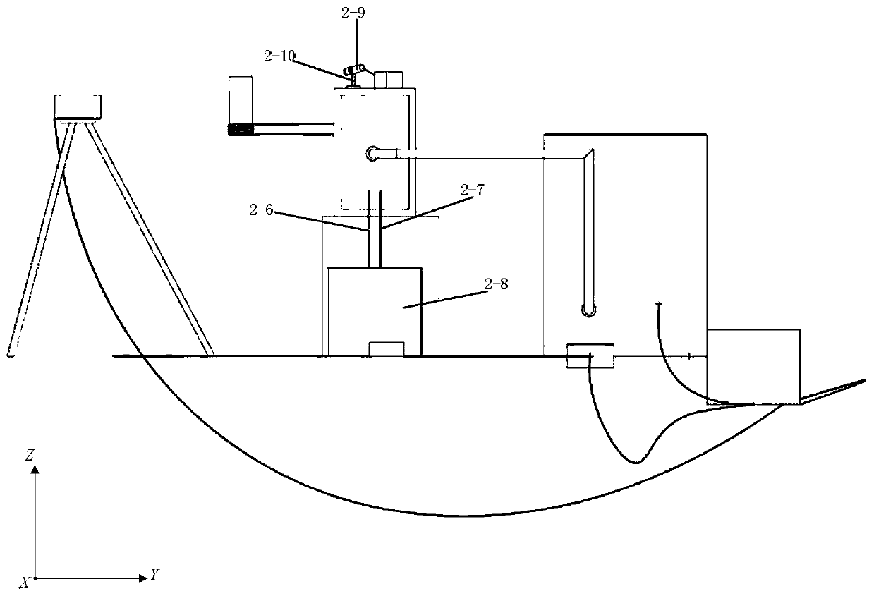
[0052] In order to solve the above-mentioned technical problems existing in the prior art, a thermal load simulation method and system for the cutting process are provided, including a heat source simulation device 1 of the machine tool feed system, a cutting heat simulation device 2 at the cutting edge of a tool, a one-way cutting A force simulation device 3, a host computer control system 4, a spindle mandrel 5 for simulating a tool, a controller 6 and a machine tool table 7.

[0053] Among them, in the heat source simulation device 1 of the feed system of the machine tool, the nickel-chromium alloy resistance wire 1-1 is wrapped between two silicon rubber insulating sheets 1-2, and the sheet platinum resistance temperature sensor 1-3 is embe...


PUM


Abstract

The invention discloses a thermo-mechanical load simulation and error detection system and method for a machine tool cutting machining process. The machine tool thermo-mechanical load simulation and error detection system comprises a machine tool working table, a spindle core rod, a controller, a control system, a cutting thermal simulation device, a one-way cutting force simulation device and a machine tool feeding system heat source simulation device, wherein the cutting thermal simulation device and the one-way cutting force simulation device are arranged on the machine tool working table. According to the thermo-mechanical load simulation and error detection system and method for the machine tool cutting machining process, a mechanism of a machine tool does not need to be dismounted from the machine tool, so that an experimental situation more accords with the actual working condition; and meanwhile, an error value can be fed back to a compensation module in a machine tool control system, the machining error can be decreased, and the machining precision can be improved.

Description

technical field [0001] The invention relates to metal cutting machine tools in the field of mechanical technology, in particular to thermal loads, cutting thermal loads and cutting force loads at various heat sources under simulated real cutting conditions of machine tools, and a detection device for tool thermal errors and force errors. Background technique [0002] There are many factors that restrict the accuracy of machine tools. Typical organic machine tool thermal errors, geometric errors, and transmission chain errors. The identification methods, modeling methods, and compensation methods for the above errors have been relatively well studied. With the popularization and application of high-speed hard cutting, difficult-to-cut materials and high-speed dry cutting, the influence of cutting load error, which was seldom considered before, on the machining accuracy of machine tools has become more and more prominent, especially the machining error caused by thermal-mechani...

Claims


Application Information

Patent Timeline
Patent Type & Authority Patents(China)
IPC IPC(8): B23Q17/09
CPCB23Q17/0952B23Q17/0985
Inventor 梁睿君何磊黄敏凯王庆伦黄江峰叶文华邵伟业
Owner NANJING UNIV OF AERONAUTICS & ASTRONAUTICS
Learn More