
Brake master pump

A technology of brake master cylinder and pump body, which is applied in the field of hydraulic equipment, can solve the problems of increased types of semi-finished products and finished products, additional burden of production scheduling, increased management difficulty, etc., and achieves the effects of reasonable structure, simplified valve body processing, and easy processing.

Pending Publication Date: 2017-12-22
镇江沃尔夫重工部件有限公司
View PDF0 Cites 0 Cited by
  • Summary
  • Abstract
  • Description
  • Claims
  • Application Information

AI Technical Summary

Problems solved by technology

This often brings additional burdens on our tooling production and production scheduling
At the same time, due to the different requirements of each customer, the eccentric direction of the oil pot interface is different, which brings great difficulties to the factory production (increased types of semi-finished and finished products, increased inventory, and increased management difficulty)

Method used


Image

  • Brake master pump
  • Brake master pump
  • Brake master pump

Examples


Embodiment Construction

[0017] The present invention will be further described below with reference to the accompanying drawings and embodiments.

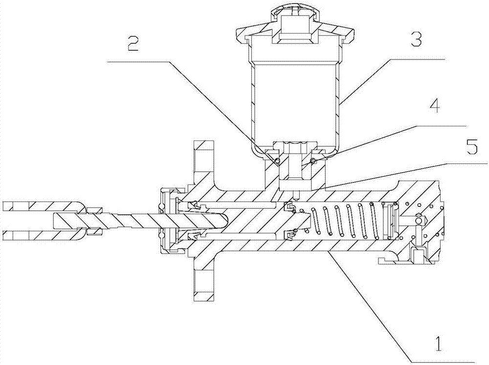
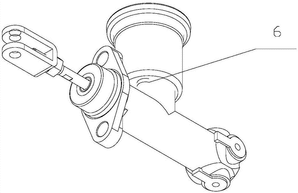
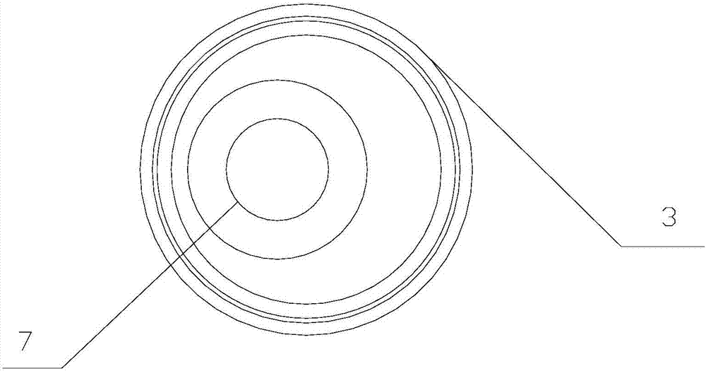
[0018] Such as Figure 1~3 As shown, a brake master cylinder includes: a pump body 1, the pump body 1 is provided with a master cylinder oiler interface 5, and the oiler assembly 3 is fixedly connected to the pump body 1 through the master cylinder oiler interface 5 Above, the oiler assembly 3 includes an oiler outlet 7 , and the oiler outlet 7 is an eccentric structure relative to the oiler assembly 3 .

[0019] An oiler sealing ring 2 is provided at the joint between the oiler assembly 3 and the master pump oiler interface 5 .

[0020] The oil pot assembly 3 is fixedly connected to the pump body 1 through oil pot pressing bolts 4 .

[0021] The oil pot assembly 3 is also provided with an oil pot stopper 6 .

[0022] The above-mentioned embodiments are only examples for clearly illustrating the present invention, rather than limiting the implementatio...


PUM


Abstract

The invention belongs to the field of hydraulic equipment, and particularly relates to a brake master pump which comprises a pump. A master pump oil can connector is arranged on the pump, an oil can assembly is fixedly connected onto the pump by the master pump oil can connector and comprises an oil can outlet, and the oil can outlet is of an eccentric structure relative to the oil can assembly. The brake master pump has the advantages that the brake master pump is reasonable in structure and easy to machine, the eccentric location of an oil can is convenient to adjust relative to the pump, and accordingly requirements of different clients can be met.

Description

technical field [0001] The invention belongs to the field of hydraulic equipment, in particular to a brake master cylinder for industrial vehicles. Background technique [0002] The brake pump assembly is a key part of the hydraulic braking system of construction machinery. The traditional structure of the brake pump is a combined structure of the oil cup and the brake pump. In the traditional structure, the oil pot is opposite to the oil inlet boss of the master cylinder valve body. Symmetrical layout structure (the oil pot is cylindrical, the oil inlet boss is also cylindrical, and the two are concentric). This traditional structure often has a small amount of interference with the oil pot due to many other parts near the master cylinder in the engine room of construction machinery. Usually, as long as the oil pot is slightly eccentric by 3-5mm, the interference problem can be solved. Therefore, customers often ask us to check the position and size of the oil inlet hole (...

Claims


Application Information

Patent Timeline
Patent Type & Authority Applications(China)
IPC IPC(8): B60T11/16B60T11/26
CPCB60T11/16B60T11/26
Inventor 肖涛龙涛
Owner 镇江沃尔夫重工部件有限公司
Learn More