Suspension beam assembly for rear suspension

A suspension beam and rear suspension technology, which is applied to the upper structure, the upper structure of the truck, transportation and packaging, etc., can solve the problems of poor stability and the inability to ensure the accuracy of the cab's whereabouts and fixation, and achieve strong stability, The effect of strong fixed effect and strong buffer function

Pending Publication Date: 2017-12-22
DONGFENG COMML VEHICLE CO LTD
View PDF13 Cites 2 Cited by
  • Summary
  • Abstract
  • Description
  • Claims
  • Application Information

AI Technical Summary

Problems solved by technology

[0007] The purpose of the present invention is to overcome the defects and problems existing in the prior art that are poor in stability and cannot ensure the accuracy of the cab's whereabouts and fixation, and provide a backrest that has good stability and can ensure the accuracy of the cab's whereabouts and fixation. Suspension beam assembly for suspension

Method used


Image

  • Suspension beam assembly for rear suspension
  • Suspension beam assembly for rear suspension
  • Suspension beam assembly for rear suspension

Examples


Embodiment 1

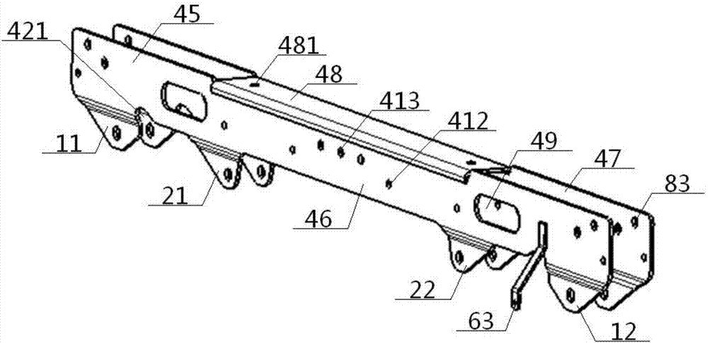
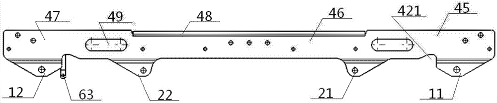
[0049] see Figure 1 to Figure 9 , a suspension beam assembly for rear suspension, comprising a suspension beam body 4 and a left first connecting portion 11, a left second connecting portion 21, a right second connecting portion 22, and a right first connecting portion 12 connected sequentially along the bottom of the suspension beam, the The first left connecting part 11 and the first right connecting part 12 are respectively hinged with the top of a vertical shock absorber 1, and the second left connecting part 21 and the second right connecting part 22 are respectively hinged with the top of a transverse shock absorber 2 ;

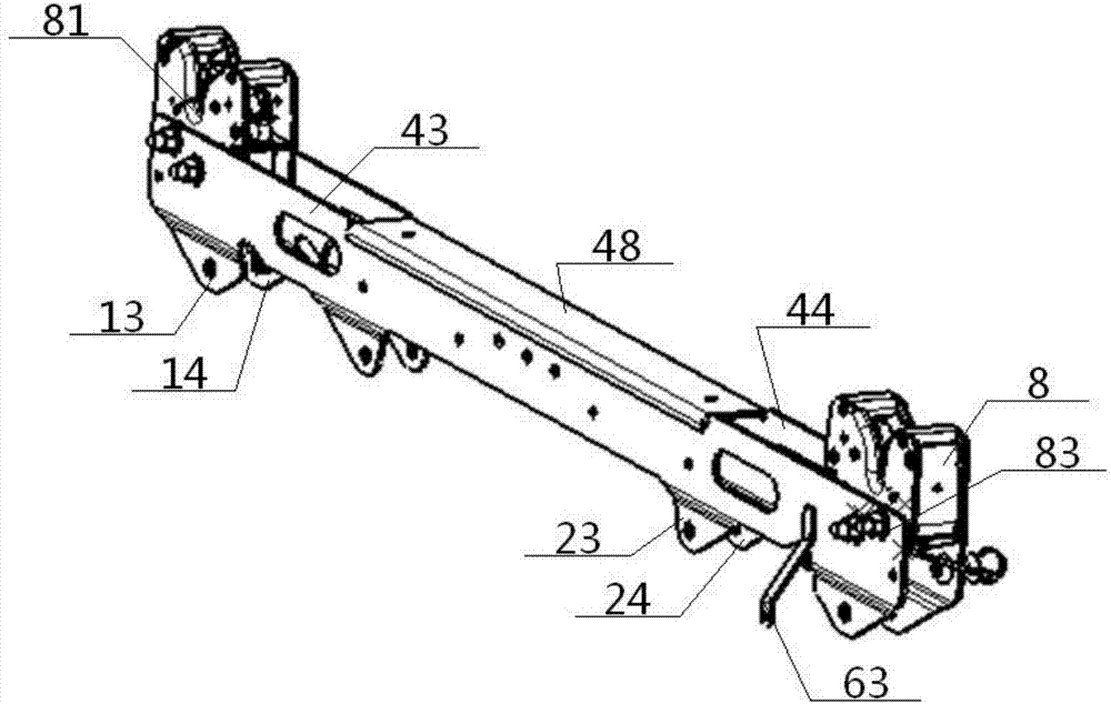
[0050] The suspension beam body 4 is sandwiched by two front floating beam plates 43 and rear floating beam plates 44 with the same structure. A hydraulic lock 8 is respectively clamped between the left and right ends of the rear floating beam plate 44, and a concave lock groove 81 is opened in the position above the suspension beam body 4 on the hydr...

Embodiment 2

[0052] Basic content is the same as embodiment 1, the difference is:

[0053] The structures of the first connecting part 11 on the left and the connecting part 12 on the right are consistent, and both include front and rear symmetrical front fins 13 and rear fins 14, and the front fins 13 are connected with the rear fins 14 through the first rotating shaft 15. The middle part of the No. 1 rotating shaft 15 is hinged to the top of the vertical shock absorber 1 sleeved on it; the second left connecting part 21 and the second right connecting part 22 have the same structure, and both include front and rear symmetrical front two wings 23 , the rear two fins 24, the front two fins 23 are connected with the rear two fins 24 by the second rotating shaft 25, and the middle part of the second rotating shaft 25 is hinged with the top of the horizontal shock absorber 2 sleeved thereon. Preferably, the type of the vertical shock absorber 1 and the transverse shock absorber 2 is a spring ...

Embodiment 3

[0055] Basic content is the same as embodiment 1, the difference is:

[0056] Described front floating beam plate 43, rear floating beam plate 44 all comprise left flat plate 45, middle flat plate 46 and right flat plate 47 connected successively, the width of left flat plate 45, right flat plate 47 is all greater than the width of middle flat plate 46, front floating beam The top of the middle plate 46 in the plate 43 is connected with the top of the middle plate 46 in the rear floating beam plate 44 by the cover plate 48, and the two ends of the cover plate 48 are provided with cover holes 481, and the left plate 45, the right plate 47 There are fixed lock holes 83 connected with the hydraulic lock 8 on the top.


PUM


Abstract

A suspension beam assembly for a rear suspension comprises a suspension beam body and a first left connecting portion, a second left connecting portion, a second right connecting portion and a first right connecting portion which are sequentially connected along the bottom of the suspension beam body. The suspension beam body is formed by clamping a front floating beam plate and a rear floating beam plate of the same structure, a hydraulic lock is clamped to portion between the left and right ends of the front floating beam plate, a hydraulic lock is clamped to the portion between the left and right ends of the rear floating beam plate, inward concave lock grooves are formed in the portions, located above the suspension beam body, of the hydraulic locks, lock hooks are arranged inside the lock grooves, and the front and rear floating beam plates each comprise a left panel, a middle panel and a right panel which are sequentially connected, wherein the widths of the left and right panels are larger than the width of the middle panel, and an overlay plate, a constraint hole, a pipeline gap, an oval through hole or a height valve adjusting rod support are arranged on the suspension beam body. The suspension beam assembly is good in stability, the falling fixing accuracy of a cab can be ensured, the manufacturing and installation costs are low, and functionality is high.

Description

technical field [0001] The invention relates to a rear suspension equipment of an automobile, in particular to a suspension beam assembly for the rear suspension, which is particularly suitable for improving the accuracy of dropping and fixing the driver's cab. Background technique [0002] At present, the truck cab is connected to the frame through the rear suspension system. The function of the rear suspension system is to support the cab, buffer the vibration caused by uneven road surface, and improve the ride comfort. [0003] The authorized announcement number is CN202163507U, and the utility model patent issued on March 14, 2012 discloses a cab rear suspension device, which includes a suspension beam assembly, a pair of combined spring shock absorber assemblies and a pair of Rear suspension vertical beams, wherein, a pair of rear suspension vertical beams are installed vertically on the lower part of a pair of combined spring damper assemblies respectively, and the two...

Claims


Application Information

Patent Timeline
Patent Type & Authority Applications(China)
IPC IPC(8): B62D33/06
CPCB62D33/0604B62D33/0608
Inventor 郭凯陈玲莉石光勇王鹏奇王庆张明
Owner DONGFENG COMML VEHICLE CO LTD
Why Eureka
Try Eureka