
Grease separation lubricated wheel reducer

A wheel-side reducer, grease separation technology, applied in the direction of gear lubrication/cooling, gear transmission, belt/chain/gear, etc. higher question

Active Publication Date: 2020-04-07
SINO TRUK JINAN POWER
View PDF6 Cites 0 Cited by
  • Summary
  • Abstract
  • Description
  • Claims
  • Application Information

AI Technical Summary

Problems solved by technology

There are also some disadvantages. The heat is generated during the meshing process of the internal gear of the wheel reducer. The wheel reducer is installed in the rim of the wheel, which makes its heat dissipation performance poor. During the braking process of the vehicle, the heat is transferred to the wheel reducer, which makes the temperature of the wheel reducer high
High temperature is easy to reduce the viscosity of the lubricating oil in the gear of the wheel reducer, and the oil seal is easy to age, resulting in the leakage of lubricating oil
[0004] Iron filings are likely to be generated during the meshing process of the internal gears of the wheel-side reducer, and enter the bearing together with the lubricating oil, causing wear to the rolling elements and raceways in the bearing, resulting in vibration and noise, and reducing the operating accuracy of the bearing

Method used


Image

  • Grease separation lubricated wheel reducer
  • Grease separation lubricated wheel reducer
  • Grease separation lubricated wheel reducer

Examples


Embodiment Construction

[0023] In order to make the object, technical solution and advantages of the present invention clearer, the present invention will be further described in detail below with reference to the accompanying drawings and examples.

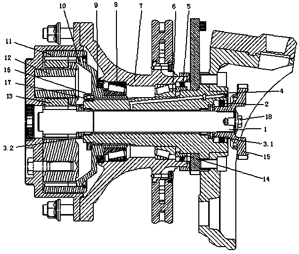
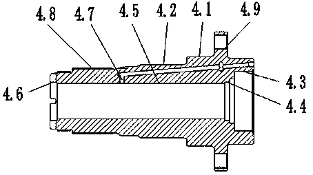
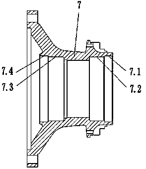
[0024] A grease separation lubricated wheel reducer, including planetary components, hubs and power input components; the input component includes an input gear shaft 1, a shaft head 4 and an input flange 15, the input gear shaft 1 runs through the center of the shaft head 4, and passes through the The first roller bearing 3.1 and the second roller bearing 3.2 are supported in the shaft head 4, the input flange 15 and the input gear shaft 1 are splined and fixed by fastening screws 18; the planetary components include a plurality of planetary wheels 13 , the planetary gear 13 meshes with the input gear shaft 1, and a plurality of planetary gears 13 are correspondingly set on the planetary gear shaft 12, and a plurality of planetary gears share a ring gea...


PUM


Abstract

The invention provides a wheel-side reducer adopting grease separating lubrication. Leakage of a gear lubricant can be reduced, and the service life of bearings can be prolonged. The wheel-side reducer comprises a planetary part, a hub and a power input part. The input part comprises an input gear shaft and a shaft head, and the planetary part comprises a plurality of planetary gears which are engaged with the input gear shaft; the planetary gear shaft is sleeved with the multiple planetary gears in a corresponding mode, and the multiple planetary gears share the same gear ring which is fixedly arranged on a gear ring support; the gear ring support is connected with the shaft head, and the planetary gears, the planetary gear shaft and the gear ring are all arranged in a wheel-side shell; the hub and the wheel-side shell are detachably connected into a whole, and the hub is supported on the shaft head and the gear ring support through the inner bearing and the outer bearing; a first oil seal is arranged between the hub and the gear ring support, and a second oil seal is arranged between the hub and the shaft head through a oil seal seat; and the inner bearing and the outer bearing are arranged in a spaced mode, and a communicating channel is arranged between the inner bearing and the outer bearing.

Description

technical field [0001] The invention relates to a wheel-side reducer, in particular to a wheel-side reducer for grease separation and lubrication, and belongs to the technical field of vehicle reducers. Background technique [0002] The wheel reducer was invented by American scientists in the 1950s. After continuous improvement, it is now widely used as a wheel reducer for mining dump truck drive axles. It is also used in some electric vehicles, which are directly driven by motors. At present, most wheel reducers in the field of vehicle engineering use planetary gear trains to transmit power to form planetary gear wheel reducers. [0003] The planetary gear wheel reducer has the advantages of compact structure, large transmission ratio, and strong bearing capacity. There are also some disadvantages. The heat is generated during the meshing process of the internal gear of the wheel reducer. The wheel reducer is installed in the rim of the wheel, which makes its heat dissipat...

Claims


Application Information

Patent Timeline
Patent Type & Authority Patents(China)
IPC IPC(8): F16H1/32F16H57/04F16H57/023
CPCF16H1/32F16H57/023F16H57/0479
Inventor 孔卓朱亮尚兴超程金林魏江龙
Owner SINO TRUK JINAN POWER
Learn More